2012 SUBARU IMPREZA WRX turn signal
[x] Cancel search: turn signalPage 276 of 416

CAUTION
. Do not place metal film or any
metal parts in the cargo area/
trunk. This may cause poor re-
ception of the signals from the
tire pressure sensors, and the
tire pressure monitoring system
will not function properly.
. FCC WARNING
Changes or modifications not
expressly approved by the party
responsible for compliance
could void the user ’s authority
to operate the equipment.
NOTE
This device complies with Part 15 of
the FCC Rules and RSS-Gen of IC
Rules. Operation is subject to the
following two conditions: (1) this de-
vice may not cause harmful interfer-
ence, and (2) this device must accept
any interference received, including
interference that may cause undesiredoperation. Parking your vehicle &
Parking brake
To set the parking brake, depress the
brake pedal firmly and hold it down until
the parking brake lever is fully pulled up.
To release the parking brake, pull the lever
up slightly, press the release button, then
lower the lever while keeping the button pressed.
When the parking brake is set while the
engine is running, the parking brake
warning light illuminates. After starting
the vehicle, be sure that the warning light
has turned off before the vehicle is driven.
Refer to “Parking brake warning ”F 3-19.
CAUTION
Never drive while the parking brake
is set because this will cause un-
necessary wear on the brake lin-
ings. Before starting to drive, always
make sure that the parking brake
has been fully released.
& Parking tips
When parking your vehicle, always per-
form the following items. . Apply the parking brake firmly.
. Put the shift lever in “1 ” (1st) for an
upgrade or “R ” (Reverse) for a down-
grade.
Never rely on the transmission alone to
hold the vehicle. Starting and operating
7-33
– CONTINUED –
Page 299 of 416
9-2In case of emergency
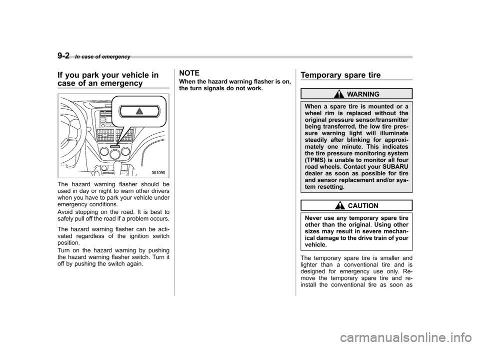
If you park your vehicle in
case of an emergency
The hazard warning flasher should be
used in day or night to warn other drivers
when you have to park your vehicle under
emergency conditions.
Avoid stopping on the road. It is best to
safely pull off the road if a problem occurs.
The hazard warning flasher can be acti-
vated regardless of the ignition switchposition.
Turn on the hazard warning by pushing
the hazard warning flasher switch. Turn it
off by pushing the switch again. NOTE
When the hazard warning flasher is on,
the turn signals do not work.
Temporary spare tire
WARNING
When a spare tire is mounted or a
wheel rim is replaced without the
original pressure sensor/transmitter
being transferred, the low tire pres-
sure warning light will illuminate
steadily after blinking for approxi-
mately one minute. This indicates
the tire pressure monitoring system
(TPMS) is unable to monitor all four
road wheels. Contact your SUBARU
dealer as soon as possible for tire
and sensor replacement and/or sys-
tem resetting.
CAUTION
Never use any temporary spare tire
other than the original. Using other
sizes may result in severe mechan-
ical damage to the drive train of yourvehicle.
The temporary spare tire is smaller and
lighter than a conventional tire and is
designed for emergency use only. Re-
move the temporary spare tire and re-
install the conventional tire as soon as
Page 305 of 416
9-8In case of emergency
WARNING
Do not use oil or grease on the
wheel studs or nuts when the spare
tire is installed. This could cause the
nuts to become loose and lead to anaccident.
14. Turn the jack handle counterclockwise
to lower the vehicle.
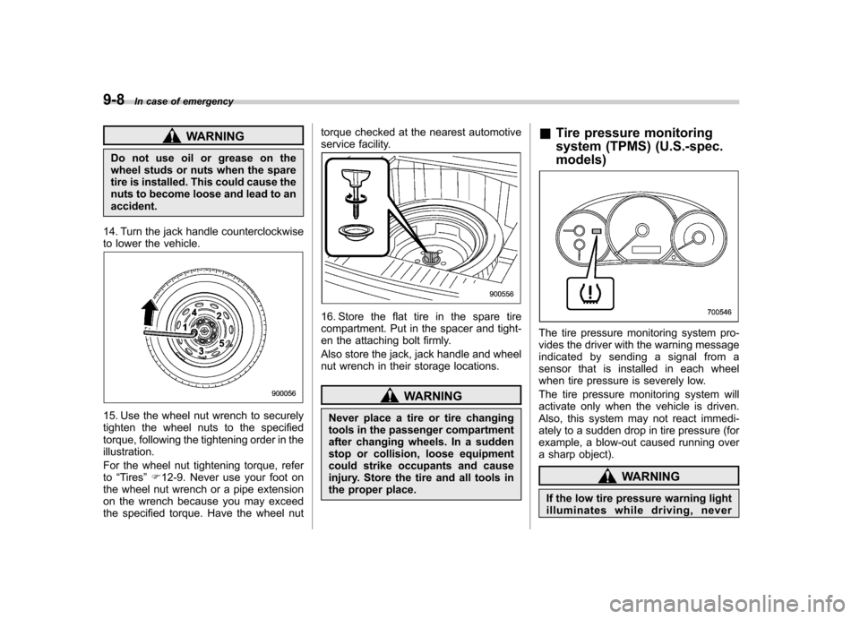
15. Use the wheel nut wrench to securely
tighten the wheel nuts to the specified
torque, following the tightening order in theillustration.
For the wheel nut tightening torque, refer to “Tires ”F 12-9. Never use your foot on
the wheel nut wrench or a pipe extension
on the wrench because you may exceed
the specified torque. Have the wheel nut torque checked at the nearest automotive
service facility.
16. Store the flat tire in the spare tire
compartment. Put in the spacer and tight-
en the attaching bolt firmly.
Also store the jack, jack handle and wheel
nut wrench in their storage locations.
WARNING
Never place a tire or tire changing
tools in the passenger compartment
after changing wheels. In a sudden
stop or collision, loose equipment
could strike occupants and cause
injury. Store the tire and all tools in
the proper place. &
Tire pressure monitoring
system (TPMS) (U.S.-spec. models)
The tire pressure monitoring system pro-
vides the driver with the warning message
indicated by sending a signal from a
sensor that is installed in each wheel
when tire pressure is severely low.
The tire pressure monitoring system will
activate only when the vehicle is driven.
Also, this system may not react immedi-
ately to a sudden drop in tire pressure (for
example, a blow-out caused running over
a sharp object).
WARNING
If the low tire pressure warning light
illuminates while driving, never
Page 323 of 416
Maintenance and serviceTire replacement .............................................. 11-29
Wheel replacement ........................................... 11-30
Aluminum wheels ............................................. 11-30
Windshield washer fluid .................................. 11-31
Replacement of wiper blades .......................... 11-32
Windshield wiper blade assembly ..................... 11-33
Windshield wiper blade rubber (type A and type B) .................................................................. 11-33
Rear window wiper blade assembly (5-door models). ......................................................... 11-34
Rear window wiper blade rubber (5-door models). ......................................................... 11-35
Battery. .............................................................. 11-36
Fuses ................................................................ 11-37 Installation of accessories
.............................. 11-39
Replacing bulbs ............................................... 11-39
Headlights (models with HID headlights) ........... 11-39
Headlights (models without HID headlights) ...... 11-39
Front turn signal light ...................................... 11-42
Front fog light (if equipped) .............................. 11-42
Rear combination lights ................................... 11-43
Back-up light (5-door) ...................................... 11-45
License plate light ........................................... 11-45
Map light ......................................................... 11-46
Dome light and cargo area light ....................... 11-47
Trunk light ....................................................... 11-47
High mount stop light (4-door) (except LED [Light Emitting Diode] type) ............................ 11-47
Other bulbs ..................................................... 11-47
Page 345 of 416
11-24Maintenance and service
!Winter (snow) tires
Winter tires are best suited for driving on
snow-covered and icy roads. However
winter tires do not perform as well as
summer tires and all season tires on roads
other than snow-covered and icy roads. & Tire pressure monitoring
system (TPMS) (if equipped)
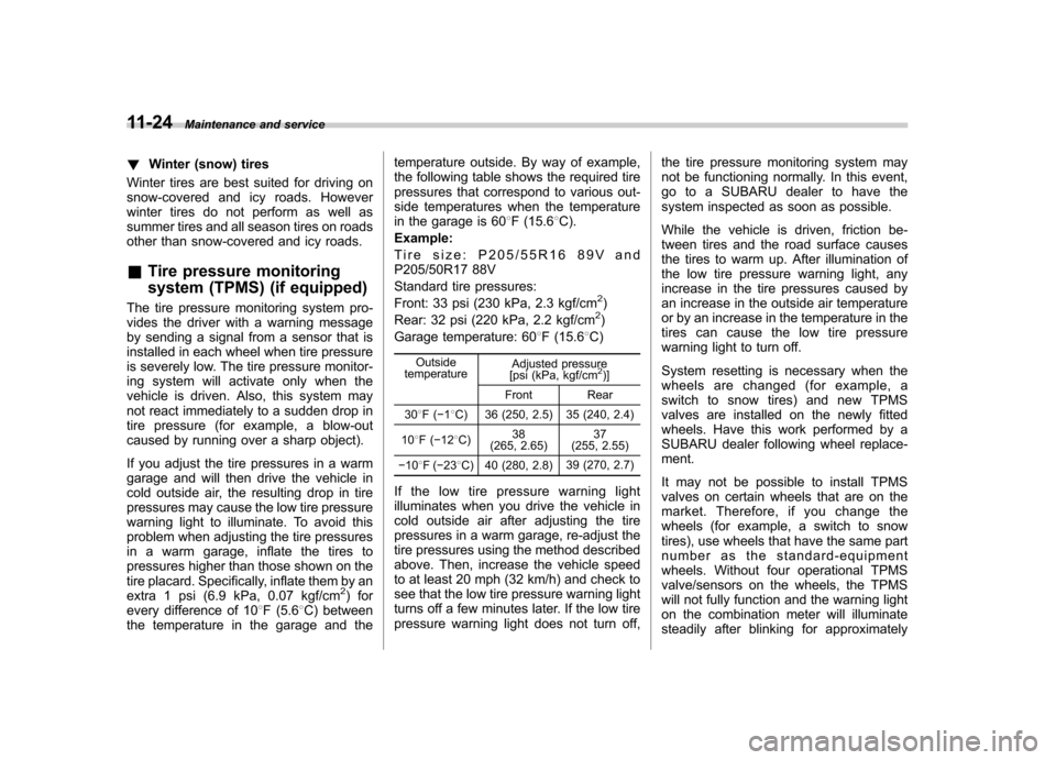
The tire pressure monitoring system pro-
vides the driver with a warning message
by sending a signal from a sensor that is
installed in each wheel when tire pressure
is severely low. The tire pressure monitor-
ing system will activate only when the
vehicle is driven. Also, this system may
not react immediately to a sudden drop in
tire pressure (for example, a blow-out
caused by running over a sharp object).
If you adjust the tire pressures in a warm
garage and will then drive the vehicle in
cold outside air, the resulting drop in tire
pressures may cause the low tire pressure
warning light to illuminate. To avoid this
problem when adjusting the tire pressures
in a warm garage, inflate the tires to
pressures higher than those shown on the
tire placard. Specifically, inflate them by an
extra 1 psi (6.9 kPa, 0.07 kgf/cm
2) for
every difference of 10 8F (5.6 8C) between
the temperature in the garage and the temperature outside. By way of example,
the following table shows the required tire
pressures that correspond to various out-
side temperatures when the temperature
in the garage is 60
8F (15.6 8C).
Example:
Tire size: P205/55R16 89V and
P205/50R17 88V
Standard tire pressures:
Front: 33 psi (230 kPa, 2.3 kgf/cm
2)
Rear: 32 psi (220 kPa, 2.2 kgf/cm2)
Garage temperature: 60 8F (15.6 8C)
Outside
temperature Adjusted pressure
[psi (kPa, kgf/cm
2)]
Front Rear
30 8F( �18C) 36 (250, 2.5) 35 (240, 2.4)
10 8F( �12 8C) 38
(265, 2.65) 37
(255, 2.55)
� 10 8F( �23 8C) 40 (280, 2.8) 39 (270, 2.7)
If the low tire pressure warning light
illuminates when you drive the vehicle in
cold outside air after adjusting the tire
pressures in a warm garage, re-adjust the
tire pressures using the method described
above. Then, increase the vehicle speed
to at least 20 mph (32 km/h) and check to
see that the low tire pressure warning light
turns off a few minutes later. If the low tire
pressure warning light does not turn off, the tire pressure monitoring system may
not be functioning normally. In this event,
go to a SUBARU dealer to have the
system inspected as soon as possible.
While the vehicle is driven, friction be-
tween tires and the road surface causes
the tires to warm up. After illumination of
the low tire pressure warning light, any
increase in the tire pressures caused by
an increase in the outside air temperature
or by an increase in the temperature in the
tires can cause the low tire pressure
warning light to turn off.
System resetting is necessary when the
wheels are changed (for example, a
switch to snow tires) and new TPMS
valves are installed on the newly fitted
wheels. Have this work performed by a
SUBARU dealer following wheel replace-ment.
It may not be possible to install TPMS
valves on certain wheels that are on the
market. Therefore, if you change the
wheels (for example, a switch to snow
tires), use wheels that have the same part
number as the standard-equipment
wheels. Without four operational TPMS
valve/sensors on the wheels, the TPMS
will not fully function and the warning light
on the combination meter will illuminate
steadily after blinking for approximately
Page 363 of 416
11-42Maintenance and service
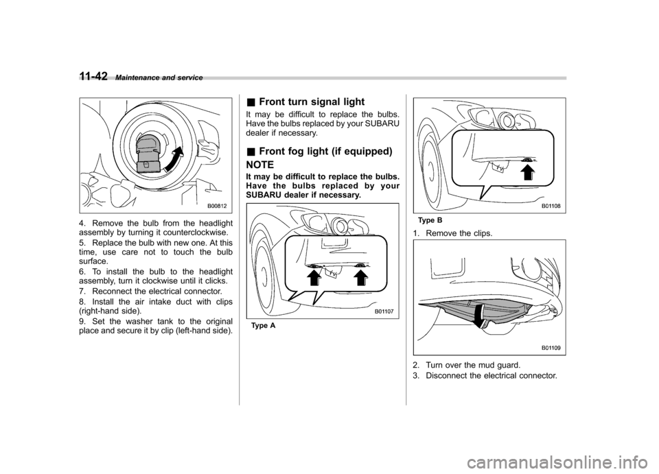
4. Remove the bulb from the headlight
assembly by turning it counterclockwise.
5. Replace the bulb with new one. At this
time, use care not to touch the bulbsurface.
6. To install the bulb to the headlight
assembly, turn it clockwise until it clicks.
7. Reconnect the electrical connector.
8. Install the air intake duct with clips
(right-hand side).
9. Set the washer tank to the original
place and secure it by clip (left-hand side). &
Front turn signal light
It may be difficult to replace the bulbs.
Have the bulbs replaced by your SUBARU
dealer if necessary. & Front fog light (if equipped)
NOTE
It may be difficult to replace the bulbs.
Have the bulbs replaced by your
SUBARU dealer if necessary.
Type A
Type B
1. Remove the clips.
2. Turn over the mud guard.
3. Disconnect the electrical connector.
Page 364 of 416
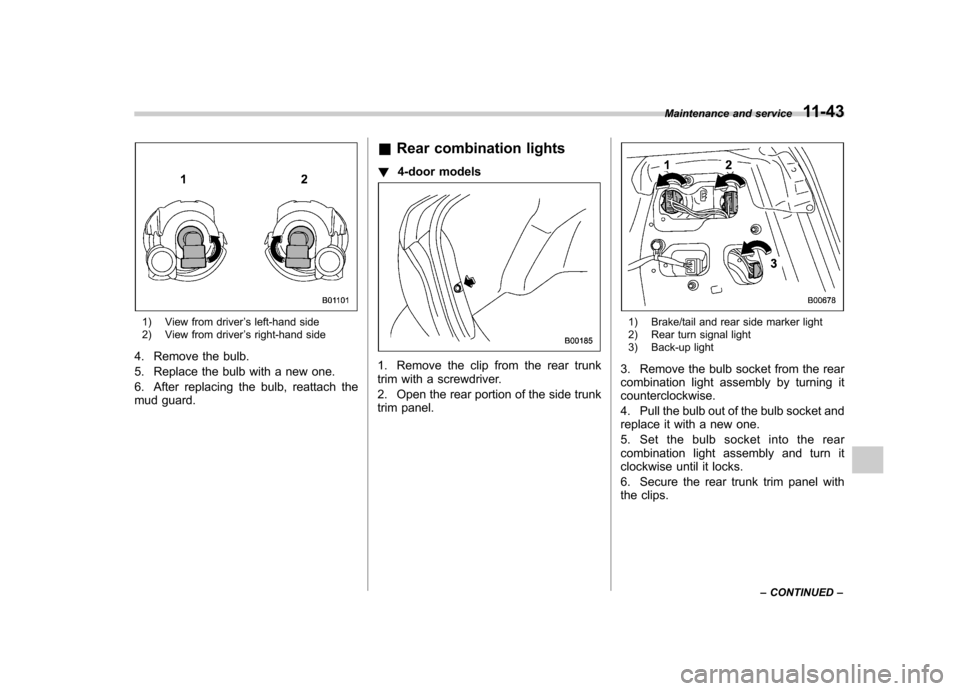
1) View from driver’s left-hand side
2) View from driver ’s right-hand side
4. Remove the bulb.
5. Replace the bulb with a new one.
6. After replacing the bulb, reattach the
mud guard. &
Rear combination lights
! 4-door models
1. Remove the clip from the rear trunk
trim with a screwdriver.
2. Open the rear portion of the side trunk
trim panel.
1) Brake/tail and rear side marker light
2) Rear turn signal light
3) Back-up light
3. Remove the bulb socket from the rear
combination light assembly by turning itcounterclockwise.
4. Pull the bulb out of the bulb socket and
replace it with a new one.
5. Set the bulb socket into the rear
combination light assembly and turn it
clockwise until it locks.
6. Secure the rear trunk trim panel with
the clips. Maintenance and service
11-43
– CONTINUED –
Page 365 of 416
11-44Maintenance and service
! 5-door models
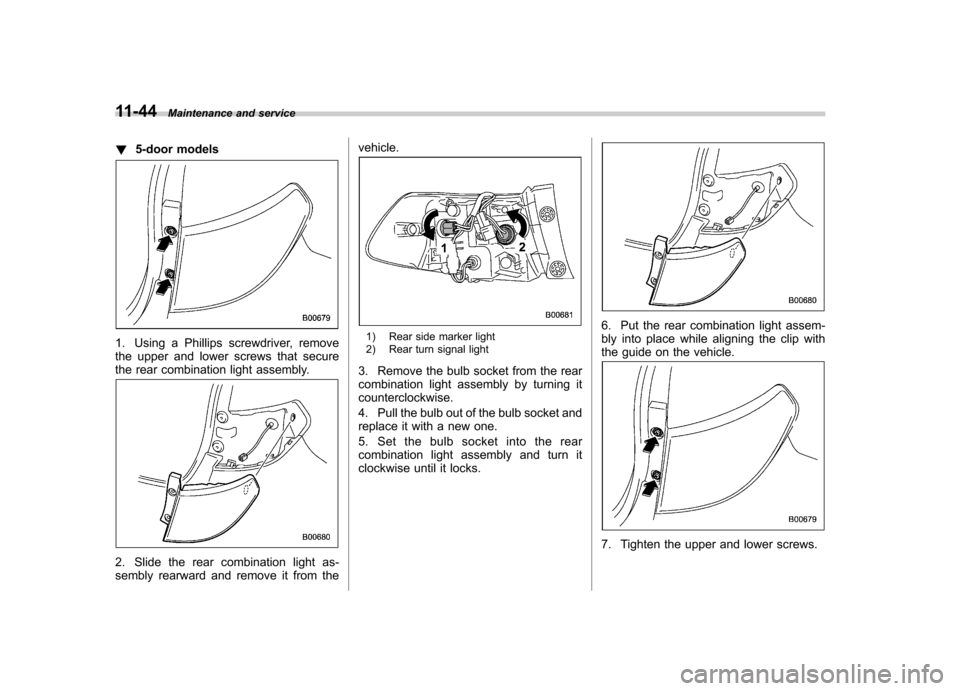
1. Using a Phillips screwdriver, remove
the upper and lower screws that secure
the rear combination light assembly.
2. Slide the rear combination light as-
sembly rearward and remove it from the vehicle.
1) Rear side marker light
2) Rear turn signal light
3. Remove the bulb socket from the rear
combination light assembly by turning itcounterclockwise.
4. Pull the bulb out of the bulb socket and
replace it with a new one.
5. Set the bulb socket into the rear
combination light assembly and turn it
clockwise until it locks.6. Put the rear combination light assem-
bly into place while aligning the clip with
the guide on the vehicle.
7. Tighten the upper and lower screws.