2012 SUBARU IMPREZA WRX torque
[x] Cancel search: torquePage 351 of 416

11-30Maintenance and service
ance between the body and tires.
It also may be dangerous and
lead to loss of vehicle control.
. You must install four tires that are
of the same size, circumference,
construction, manufacturer,
brand (tread pattern), degree of
wear, speed symbol and load
index. Mixing tires of different
types, sizes or degrees of wear
can result in damage to the
vehicle ’s power train. Use of
different types or sizes of tires
can also dangerously reduce
controllability and braking per-
formance and can lead to anaccident.
. Use only radial tires. Do not use
radial tires together with belted
bias tires and/or bias-ply tires.
Doing so can dangerously re-
duce controllability, resulting in
an accident.
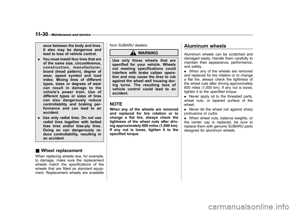
& Wheel replacement
When replacing wheels due, for example,
to damage, make sure the replacement
wheels match the specifications of the
wheels that are fitted as standard equip-
ment. Replacement wheels are available from SUBARU dealers.
WARNING
Use only those wheels that are
specified for your vehicle. Wheels
not meeting specifications could
interfere with brake caliper opera-
tion and may cause the tires to rub
against the wheel well housing dur-
ing turns. The resulting loss of
vehicle control could lead to anaccident.
NOTE
When any of the wheels are removed
and replaced for tire rotation or to
change a flat tire, always check the
tightness of the wheel nuts after driv-
ing approximately 600 miles (1,000 km).
If any nut is loose, tighten it to the
specified torque. Aluminum wheels
Aluminum wheels can be scratched and
damaged easily. Handle them carefully to
maintain their appearance, performance,
and safety. .
When any of the wheels are removed
and replaced for tire rotation or to change
a flat tire, always check the tightness of
the wheel nuts after driving approximately
600 miles (1,000 km). If any nut is loose,
tighten it to the specified torque. . Never apply oil to the threaded parts,
wheel nuts, or tapered surface of the wheel. . Never let the wheel rub against sharp
protrusions or curbs.. When wheel nuts, balance weights, or
the center cap is replaced, be sure to
replace them with genuine SUBARU parts
designed for aluminum wheels.
Page 378 of 416

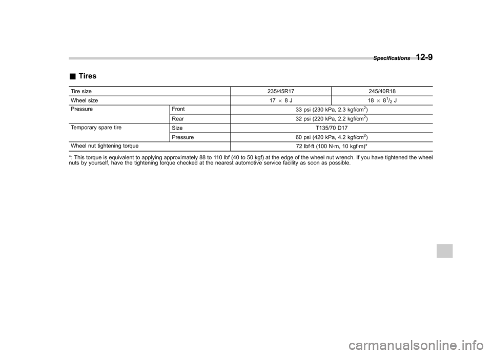
&Tires
Tire size 235/45R17 245/40R18
Wheel size 1768J 18 68
1/2J
Pressure Front 33 psi (230 kPa, 2.3 kgf/cm2)
Rear 32 psi (220 kPa, 2.2 kgf/cm2)
Temporary spare tire Size T135/70 D17
Pressure 60 psi (420 kPa, 4.2 kgf/cm
2)
Wheel nut tightening torque 72 lbf·ft (100 N·m, 10 kgf·m)*
*: This torque is equivalent to applying approximately 88 to 110 lbf (40 to 50 kgf) at the edge of the wheel nut wrench. If you have tightened the wheel
nuts by yourself, have the tightening torque checked at the nearest automotive service facility as soon as possible. Specifications
12-9
Page 397 of 416

13-10Consumer information and Reporting safety defects
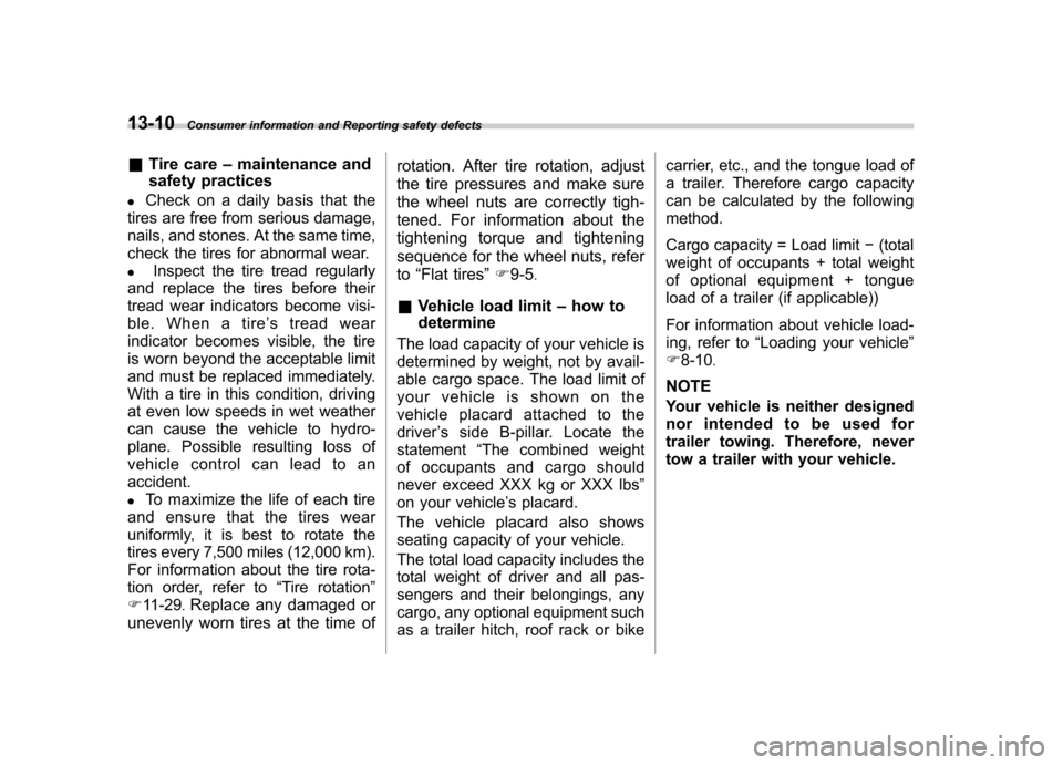
& Tire care –maintenance and
safety practices
. Check on a daily basis that the
tires are free from serious damage,
nails, and stones. At the same time,
check the tires for abnormal wear. . Inspect the tire tread regularly
and replace the tires before their
tread wear indicators become visi-
ble. When a tire ’streadwear
indicator becomes visible, the tire
is worn beyond the acceptable limit
and must be replaced immediately.
With a tire in this condition, driving
at even low speeds in wet weather
can cause the vehicle to hydro-
plane. Possible resulting loss of
vehiclecontrolcanleadtoanaccident. . To maximize the life of each tire
and ensure that the tires wear
uniformly, it is best to rotate the
tires every 7,500 miles (12,000 km).
For information about the tire rota-
tion order, refer to “Tire rotation ”
F 11-29 .
Replace any damaged or
unevenly worn tires at the time of rotation. After tire rotation, adjust
the tire pressures and make sure
the wheel nuts are correctly tigh-
tened. For information about the
tightening torque and tightening
sequence for the wheel nuts, refer to
“Flat tires ”F 9-5 .
& Vehicle load limit –how to
determine
The load capacity of your vehicle is
determined by weight, not by avail-
able cargo space. The load limit of
your vehicle is shown on the
vehicle placard attached to the
driver ’s side B-pillar. Locate the
statement “The combined weight
of occupants and cargo should
never exceed XXX kg or XXX lbs ”
on your vehicle ’s placard.
Thevehicleplacardalsoshows
seating capacity of your vehicle.
The total load capacity includes the
total weight of driver and all pas-
sengers and their belongings, any
cargo, any optional equipment such
as a trailer hitch, roof rack or bike carrier, etc., and the tongue load of
a trailer. Therefore cargo capacity
can be calculated by the following method.
Cargo capacity = Load limit
�(total
weight of occupants + total weight
of optional equipment + tongue
load of a trailer (if applicable))
For information about vehicle load-
ing, refer to “Loading your vehicle ”
F 8-10 .
NOTE
Your vehicle is neither designed
nor intended to be used for
trailer towing. Therefore, never
tow a trailer with your vehicle.
Page 413 of 416

14-10Index
Tools .......................................................................... 9-3
Top tether anchorages ........................................ 1-29, 1-31
Towing ...................................................................... 9-12
All wheels on the ground ........................................ 9-15
Flat-bed truck ........................................................ 9-15
Hooks ................................................................... 9-13
Trailer Towing .................................................................. 8-13
Trip meter ................................................................... 3-7
Trunk lid ................................................................... 2-23
Release handle ..................................................... 2-24
Trunk light ................................................................ 11-47
Turn signal
Indicator lights ....................................................... 3-24
Lever .................................................................... 3-30
U
Under-floor storage compartment ................................. 6-14
USB storage device operations .................................... 5-26
V
Valet mode ................................................................ 2-17
Vanity mirror ................................................................ 6-4
Vehicle Capacity weight ..................................................... 8-10
Identification ........................................................ 12-17
Symbols .................................................................... 3
Vehicle Dynamics Control Mode switch .......................................................... 7-29
OFF indicator light .................................................. 3-21
OFF switch ........................................................... 7-30 Operation indicator light
................................... 3-20, 3-21
System .................................................................. 7-28
Warning light .......................................................... 3-20
Ventilator .................................................................... 4-2
W
Warning and indicator lights ......................................... 3-12
Warning light ABS...................................................................... 3-18
Brake system ......................................................... 3-19
Charge .................................................................. 3-16
CHECK ENGINE .................................................... 3-15
Door open ............................................................. 3-20
Driver ’s Control Center Differential ............................ 3-25
Hill start assist ....................................................... 3-20
Low fuel ................................................................ 3-20
Low tire pressure .................................................... 3-16
Oil pressure ........................................................... 3-16
Rear differential oil temperature ................................ 3-16
Seatbelt. ................................................................ 3-13
SRS airbag system ................................................. 3-14
Vehicle Dynamics Control ........................................ 3-20
Warranties ..................................................................... 1
Washing .................................................................... 10-2
Waxing and polishing .................................................. 10-3
Wear indicators ........................................................ 11-28
Wheel
Aluminum ............................................................ 11-30
Balance ............................................................... 11-27
Nut tightening torque ........................................ 9-5, 12-9
Replacement. ....................................................... 11-30