2012 SUBARU IMPREZA WRX brake
[x] Cancel search: brakePage 137 of 416
3-20Instruments and controls
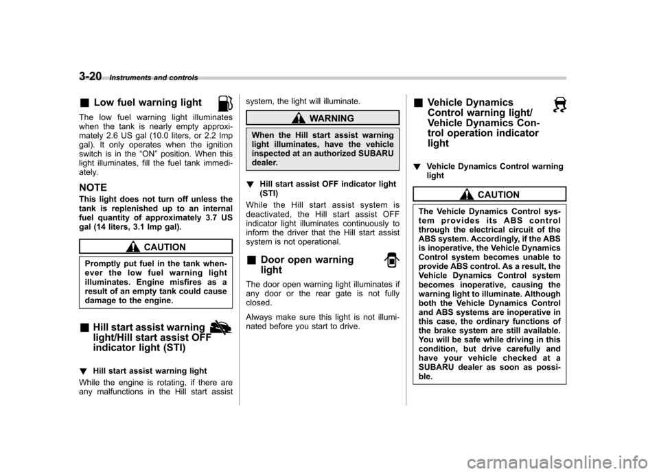
&Low fuel warning light
The low fuel warning light illuminates
when the tank is nearly empty approxi-
mately 2.6 US gal (10.0 liters, or 2.2 Imp
gal). It only operates when the ignition
switch is in the “ON ”position. When this
light illuminates, fill the fuel tank immedi-
ately. NOTE
This light does not turn off unless the
tank is replenished up to an internal
fuel quantity of approximately 3.7 US
gal (14 liters, 3.1 Imp gal).
CAUTION
Promptly put fuel in the tank when-
ever the low fuel warning light
illuminates. Engine misfires as a
result of an empty tank could cause
damage to the engine.
& Hill start assist warning
light/Hill start assist OFF
indicator light (STI)
!Hill start assist warning light
While the engine is rotating, if there are
any malfunctions in the Hill start assist system, the light will illuminate.
WARNING
When the Hill start assist warning
light illuminates, have the vehicle
inspected at an authorized SUBARU
dealer.
! Hill start assist OFF indicator light(STI)
While the Hill start assist system is
deactivated, the Hill start assist OFF
indicator light illuminates continuously to
inform the driver that the Hill start assist
system is not operational. & Door open warning light
The door open warning light illuminates if
any door or the rear gate is not fullyclosed.
Always make sure this light is not illumi-
nated before you start to drive. &
Vehicle Dynamics
Control warning light/
Vehicle Dynamics Con-
trol operation indicatorlight
!Vehicle Dynamics Control warning light
CAUTION
The Vehicle Dynamics Control sys-
tem provides its ABS control
through the electrical circuit of the
ABS system. Accordingly, if the ABS
is inoperative, the Vehicle Dynamics
Control system becomes unable to
provide ABS control. As a result, the
Vehicle Dynamics Control system
becomes inoperative, causing the
warning light to illuminate. Although
both the Vehicle Dynamics Control
and ABS systems are inoperative in
this case, the ordinary functions of
the brake system are still available.
You will be safe while driving in this
condition, but drive carefully and
have your vehicle checked at a
SUBARU dealer as soon as possi-ble.
Page 138 of 416

NOTE .If the electrical circuit of the Vehicle
Dynamics Control system itself mal-
functions, only this particular warning
light illuminates. Under these circum-
stances, the ABS (Anti-lock Brake
System) remains fully operational.. The warning light illuminates when
the electronic control system of the
ABS/Vehicle Dynamics Control systemmalfunctions.
The Vehicle Dynamics Control system is
probably inoperative under any of the
following conditions. Have your vehicle
checked at a SUBARU dealer immedi-
ately. . The warning light does not illuminate
when the ignition switch is turned to the “ ON ”position.
. The warning light illuminates while the
vehicle is running.
NOTE
If the warning light behavior is as
described in the following examples,
the Vehicle Dynamics Control system
may be considered to be operating
normally. . The warning light illuminates right
after the engine is started but turns off
immediately and remains off.. The warning light illuminates after the engine has started and turns off
while the vehicle is subsequently beingdriven..
The warning light illuminates during
driving, but turns off immediately and
remains off. ! Vehicle Dynamics Control opera-
tion indicator light
The indicator light flashes during activa-
tion of the skid suppression function and
during activation of the traction controlfunction. NOTE . The light may remain illuminated for
a short period of time after the engine
has been started, especially in cold
weather. This does not indicate the
existence of a problem. The light
should turn off as soon as the engine
has warmed up.. The indicator light illuminates when
the engine has developed a problem
and the CHECK ENGINE warning light/
malfunction indicator light is on.
The Vehicle Dynamics Control system is
probably malfunctioning under the follow-
ing condition. Have your vehicle checked
at a SUBARU dealer as soon as possible. . The light does not turn off even after
the engine has warmed up for several minutes after it was started. &
Vehicle Dynamics
Control OFF indicator
light/Traction Control
OFF indicator light (STI)
This light has the function of indicating the
following conditions. .The Vehicle Dynamics Control system
has been deactivated (all models).. Only the Traction control system has
been deactivated (STI).
The light illuminates under the following conditions. . The Vehicle Dynamics Control system
is not operating (all models).. Only the Traction Control system is not
operating (STI). STI:
This light illuminates in yellow for approxi-
mately 1 second when the ignition switch
is turned to the “ON ”position. After that,
the light changes to green and remains
illuminated in green for 1 second, and then
turns off. It indicates that the Vehicle
Dynamics Control system is operating
normally. Instruments and controls
3-21
– CONTINUED –
Page 147 of 416
3-30Instruments and controls
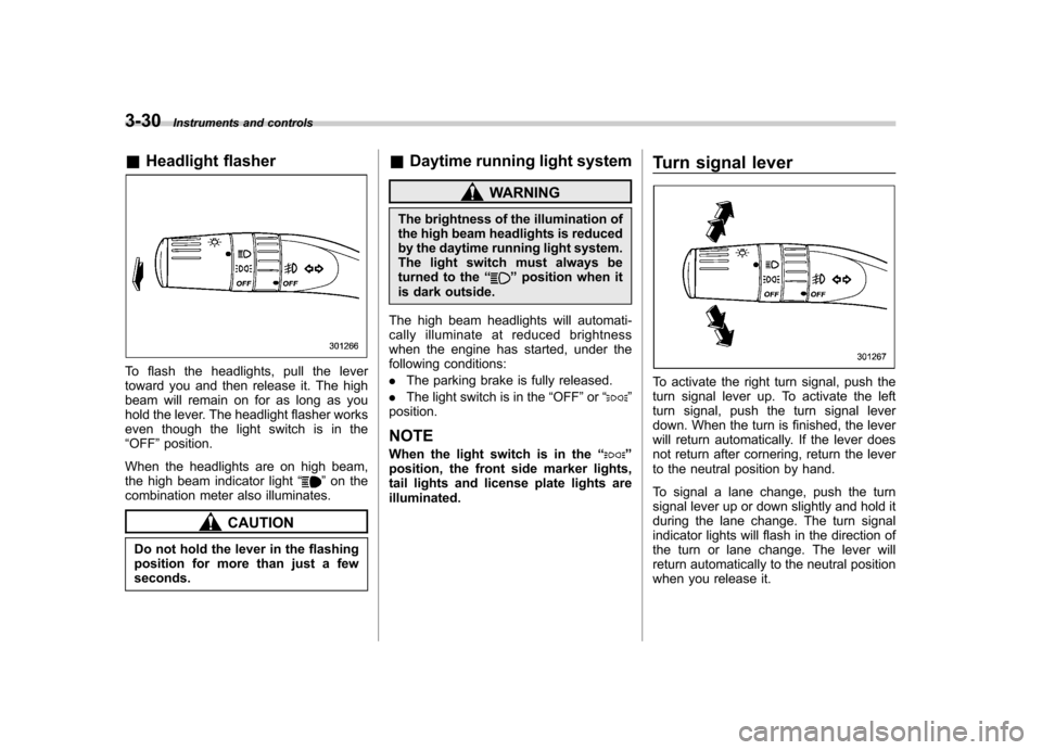
&Headlight flasher
To flash the headlights, pull the lever
toward you and then release it. The high
beam will remain on for as long as you
hold the lever. The headlight flasher works
even though the light switch is in the“OFF ”position.
When the headlights are on high beam,
the high beam indicator light “
”on the
combination meter also illuminates.
CAUTION
Do not hold the lever in the flashing
position for more than just a fewseconds. &
Daytime running light system
WARNING
The brightness of the illumination of
the high beam headlights is reduced
by the daytime running light system.
The light switch must always be
turned to the “
”position when it
is dark outside.
The high beam headlights will automati-
cally illuminate at reduced brightness
when the engine has started, under the
following conditions: . The parking brake is fully released.
. The light switch is in the “OFF ”or “
”
position. NOTE
When the light switch is in the “
”
position, the front side marker lights,
tail lights and license plate lights areilluminated. Turn signal lever
To activate the right turn signal, push the
turn signal lever up. To activate the left
turn signal, push the turn signal lever
down. When the turn is finished, the lever
will return automatically. If the lever does
not return after cornering, return the lever
to the neutral position by hand.
To signal a lane change, push the turn
signal lever up or down slightly and hold it
during the lane change. The turn signal
indicator lights will flash in the direction of
the turn or lane change. The lever will
return automatically to the neutral position
when you release it.
Page 235 of 416
6-6Interior equipment
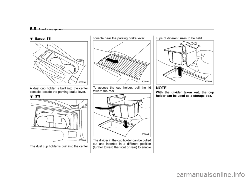
! Except STI
A dual cup holder is built into the center
console, beside the parking brake lever. !STI
The dual cup holder is built into the center console near the parking brake lever.
To access the cup holder, pull the lid
toward the rear.
The divider in the cup holder can be pulled
out and inserted in a different position
(further toward the front or rear) to enablecups of different sizes to be held.
NOTE
With the divider taken out, the cup
holder can be used as a storage box.
Page 238 of 416
tight for the accessory power
outlet, this can result in a poor
contact or cause the plug to get
stuck. Only use plugs that fit
properly.
. Use of an electric appliance in the
accessory power outlet for a long
period of time while the engine is
not running can cause batterydischarge.
. Before driving your vehicle, make
sure that the plug and the cord
on your electrical appliance will
not interfere with your shifting
gears and operating the accel-
erator and brake pedals. If they
do, do not use the electrical
appliance while driving. &
Use with a cigarette lighter (if equipped)
To use the accessory power outlet below
the climate control as a cigarette lighter
socket, purchase the cigarette lighter plug,
which is an optional accessory. A cigarette
lighter plug is available from your
SUBARU dealer.
The cigarette lighter operates only when
the ignition switch is in the “ON ”or “Acc ”
position.
To use the cigarette lighter, push in the
knob and wait a few moments. It will
automatically spring up when ready foruse.
WARNING
To avoid being burned, never grasp
the lighter by the end with the
heating element. Doing so could
result in injury and could also
damage the heating element.
CAUTION
. Do not hold the lighter pushed in,
because it will overheat.
. The electrical power socket lo-
cated in the center console is
originally designed to use a gen- uine SUBARU cigarette lighter
plug. Do not use a non-genuine
cigarette lighter plug in the sock-
et. Doing so may cause a short-
circuit and overheating, resulting
in a fire.
. If the socket is ever used for a
plug-in accessory such as a cell
phone, that may damage the
portion of the socket ’s internal
mechanism that causes a cigar-
ette lighter plug to “pop out ”
after its lighter element is heated.
Therefore, do not place a cigar-
ette lighter plug in a socket that
has been used, even once, to
power a plug-in accessory. Doing
so may cause the plug to stick
and overheat, creating a potential
fire hazard. Interior equipment
6-9
Page 244 of 416
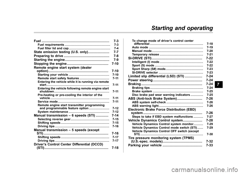
Fuel...................................................................... 7-3
Fuel requirements ............................................... 7-3
Fuel filler lid and cap ........................................... 7-4
State emission testing (U.S. only) ...................... 7-7
Preparing to drive ............................................... 7-8
Starting the engine .............................................. 7-9
Stopping the engine ........................................... 7-10
Remote engine start system (dealer option) .............................................................. 7-10
Starting your vehicle .......................................... 7-10
Remote start safety features ............................... 7-11
Entering the vehicle while it is running via remote start ................................................................. 7-11
Entering the vehicle following remote engine start shutdown ......................................................... 7-11
Pre-heating or pre-cooling the interior of the vehicle ............................................................. 7-11
Service mode ..................................................... 7-11
Remote engine start transmitter programming and programmable feature option ..................... 7-12
System maintenance .......................................... 7-12
Manual transmission –6 speeds (STI) ............. 7-14
Selecting reverse gear ........................................ 7-15
Shifting speeds .................................................. 7-15
Driving tips ........................................................ 7-16
Manual transmission –5 speeds (except
STI) ................................................................... 7-16
Shifting speeds .................................................. 7-17
Driving tips ........................................................ 7-17
Driver ’s Control Center Differential (DCCD)
(STI) .................................................................. 7-18 To change mode of driver
’s control center
differential ....................................................... 7-18
Auto mode ........................................................ 7-19
Manual mode ..................................................... 7-20
Temporary release ............................................. 7-21
SI-DRIVE (STI) .................................................... 7-22
Intelligent (I) mode ............................................. 7-22
Sport (S) mode .................................................. 7-22
Sport Sharp (S#) mode. ...................................... 7-23
SI-DRIVE selector .............................................. 7-23
Limited slip differential (LSD) (STI) .................. 7-24
Power steering ................................................... 7-24
Braking ............................................................... 7-24
Braking tips ....................................................... 7-24
Brake system .................................................... 7-25
Disc brake pad wear warning indicators ............. 7-25
ABS (Anti-lock Brake System) .......................... 7-26
ABS system self-check ...................................... 7-26
ABS warning light .............................................. 7-26
Electronic Brake Force Distribution (EBD) system ............................................................. 7-26
Steps to take if EBD system malfunctions ..... ..... 7-27
Vehicle Dynamics Control system .................... 7-28
Vehicle Dynamics Control system monitor..... ..... 7-29
Vehicle Dynamics Control mode switch (STI) . ..... 7-29
Vehicle Dynamics Control OFF switch (except STI) ................................................................. 7-30
Tire pressure monitoring system (TPMS) (U.S.-spec. models). ........................................ 7-32
Parking your vehicle ......................................... 7-33
Starting and operating
7
Page 245 of 416

Starting and operatingParking brake ..................................................... 7-33
Parking tips ....................................................... 7-33
Hill start assist system ...................................... 7-35
To activate/deactivate the Hill start assist system (STI) ................................................................. 7-35
Hill start assist warning light/Hill start assist OFF indicator light ................................................... 7-37 Cruise control
.................................................... 7-37
To set cruise control .......................................... 7-37
To temporarily cancel the cruise control ............. 7-38
To turn off the cruise control .............................. 7-39
To change the cruising speed ............................ 7-39
Cruise control indicator light .............................. 7-40
Cruise control set indicator light ... ..................... 7-40
Page 251 of 416
7-8Starting and operating
.A vehiclefails the OBDII inspection if
the “CHECK ENGINE ”warning light is not
properly operating (light is illuminated or is
not working due to a burned out bulb) or
there is one or more diagnostic trouble
codes stored in the vehicle ’s computer.
. A state emission inspection may reject
(not pass or fail) a vehicle if the number of
OBDII system readiness monitors “NOT
READY ”is greater than one. If the
vehicle ’s battery has been recently re-
placed or disconnected, the OBDII system
inspection may indicate that the vehicle is
not ready for the emission test. Under this
condition, the vehicle driver should be
instructed to drive his/her vehicle for a few
days to reset the readiness monitors and
return for an emission re-inspection. . Owners of rejected or failing vehicles
should contact their SUBARU Dealer for service.
Some states still use dynamometers in
their emission inspection program. A
dynamometer is a treadmill or roller-like
testing device that allows your vehicle ’s
wheels to turn while the vehicle remains in
one place. Prior to your vehicle being put
on a dynamometer, tell your emission
inspector
not to place your SUBARU
AWD vehicle on a two-wheel dynam-
ometer. Otherwise, serious transmis-
sion damage will result. The U.S. Environmental Protection
Agency (EPA) and states using two-wheel
dynamometers in their emission testing
program have EXEMPTED SUBARU
AWD vehicles from the portion of the
testing program that involves a two-wheel
dynamometer. There are some states that
use four-wheel dynamometers in their
testing program. When properly used, this
equipment should not damage a SUBARU
AWD vehicle.
Under no circumstances should the rear
wheels be jacked off the ground, nor
should the driveshaft be disconnected for
state emission testing.
Preparing to drive
You should perform the following checks
and adjustments every day before you
start driving.
1. Check that all windows, mirrors, and
lights are clean and unobstructed.
2. Check the appearance and condition
of the tires. Also check tires for properinflation.
3. Look under the vehicle for any sign of leaks.
4. Check that the hood, trunk (4-door)
and rear gate (5-door) are fully closed.
5. Check the adjustment of the seat.
6. Check the adjustment of the inside
and outside mirrors.
7. Fasten your seatbelt. Check that your
passengers have fastened their seatbelts.
8. Check the operation of the warning
and indicator lights when the ignition
switch is turned to the
“ON ”position.
9. Check the gauges, indicator and warn-
ing lights after starting the engine.
NOTE
Engine oil, engine coolant, brake fluid,
washer fluid and other fluid levels
should be checked daily, weekly or at
fuel stops.