2012 SUBARU FORESTER Bulbs
[x] Cancel search: BulbsPage 15 of 438

12
Illustrated index &Exterior1) Engine hood (page 11-5)
2) Headlight switch (page 3-30)
3) Replacing bulbs (page 11-45)
4) Wiper switch (page 3-34)
5) Moonroof (page 2-24)
6) Roof rail (page 8-14)
7) Door locks (page 2-4)
8) Tire pressure (page 11-31)
9) Flat tires (page 9-6)
10) Tire chains (page 8-11)
11) Front fog light switch (page 3-32)
12) Tie-down hooks (page 9-14)
13) Towing hook (page 9-14)
Page 123 of 438

3-12Instruments and controls
&ECO gauge (models with type
A combination meter)
The unit displayed varies depending on
the model.
The ECO gauge shows the difference
between the average rate of fuel con-
sumption since the trip meter was last
reset and the current rate of fuel con-sumption.
The ECO gauge indicates the current fuel
efficiency as shown in the following chart.
Displayed unit Needle pointing
“ + ” side “-” side
MPG Better Poorer
l/100km Poorer BetterNOTE .
The ECO gauge shows only an
approximate indication of fuel effi-
ciency.. After resetting the trip meter, the
average rate of fuel consumption is not
shown until driving 0.6 mile (1 km).
Until that time, the ECO gauge does notoperate. Warning and indicator lights
Several of the warning and indicator lights
illuminate when the ignition switch is
initially turned to the
“ON ”position. This
permits checking the operation of thebulbs.
Apply the parking brake and turn the
ignition switch to the “ON ”position. For
the system check, the following lights
illuminate and turn off after several sec-
onds or after the engine has started.
: Seatbelt warning light (The seatbelt warning light turns off
only when the driver fastens theseatbelt.)
: Front passenger ’s seatbelt warning
light
(The seatbelt warning light turns off
only when the front seat passenger
fastens the seatbelt.)
: SRS airbag system warning light
ON /
: Front passenger ’s frontal airbag
ON indicator light
/: Front passenger ’s frontal airbag
OFF indicator light
: CHECK ENGINE warning light/Mal- function indicator light
Page 135 of 438

3-24Instruments and controls
equipped with the security alarm system
and the immobilizer system.
This indicator light shows the status of the
alarm system. It also indicates operation
of the immobilizer system. ! Alarm system
It blinks to show the driver the operational
status of the alarm system. For detailed
information, refer to “Alarm system ”F 2-
14. ! Immobilizer system
This light blinks approximately 60 seconds
after the ignition switch is turned from“ ON ”position to the “Acc ”or “LOCK ”
position or immediately after the key is
pulled out. Refer to “Immobilizer ”F 2-3.
If the indicator light does not flash, it may
indicate that immobilizer system may be
malfunctioning. Contact your nearest
SUBARU dealer immediately.
In the event that an unauthorized key (for
example, an unauthorized duplicate) is
used, the security indicator light illumi-nates.
NOTE
Even if the security indicator light
flashes irregularly or its fuse blows
(the light does not flash if its fuse is
blown), the immobilizer system will function normally.
& SPORT mode indicator
light (AT models)
When the select lever is moved to the
manual gate, the SPORT mode is se-
lected and the indicator light illuminates.
Refer to “SPORT mode ”F 7-20.
& Select lever and gear posi-
tion indicator (AT models)
Type A
Type B
This indicator shows the position of the
select lever.
When the manual mode is selected, the
gear position indicator (which shows the
current gear selection) and the upshift/
downshift indicator light up. Refer to“ Automatic transmission ”F 7-15.
& Turn signal indicator lights
These lights show the operation of the turn
signal or lane change signal.
If the indicator lights do not blink or blink
rapidly, any of the turn signal light bulbs
may be burned out. Replace the bulb as
soon as possible. Refer to “Replacing
bulbs ”F 11-45.
Page 341 of 438

Maintenance and serviceTires and wheels .............................................. 11-29
Types of tires ................................................... 11-29
Tire pressure monitoring system (TPMS) (U.S.-spec. models) ........................................ 11-29
Tire inspection ................................................. 11-31
Tire pressures and wear ................................... 11-31
Wheel balance .................................................. 11-33
Wear indicators ................................................ 11-34
Tire rotation direction mark .............................. 11-34
Tire rotation ..................................................... 11-35
Tire replacement .............................................. 11-35
Wheel replacement ........................................... 11-36
Wheel covers (if equipped) ............................... 11-36
Aluminum wheels ............................................. 11-37
Windshield washer fluid .................................. 11-37
Replacement of wiper blades .......................... 11-39
Windshield wiper blade assembly ..................... 11-39Windshield wiper blade rubber
......................... 11-40
Rear window wiper blade assembly .................. 11-41
Rear window wiper blade rubber ... ................... 11-41
Battery .............................................................. 11-43
Fuses ................................................................ 11-44
Installation of accessories .............................. 11-45
Replacing bulbs ............................................... 11-45
Headlights (models with HID headlights) ........... 11-45
Headlights (models without HID headlights) ...... 11-46
Position light ................................................... 11-48
Front turn signal light ...................................... 11-48
Rear combination lights ................................... 11-48
License plate light ........................................... 11-49
Dome light, map light, cargo area light and door step light ............................................... 11-50
Other lights on the vehicle ............................... 11-51
Page 384 of 438

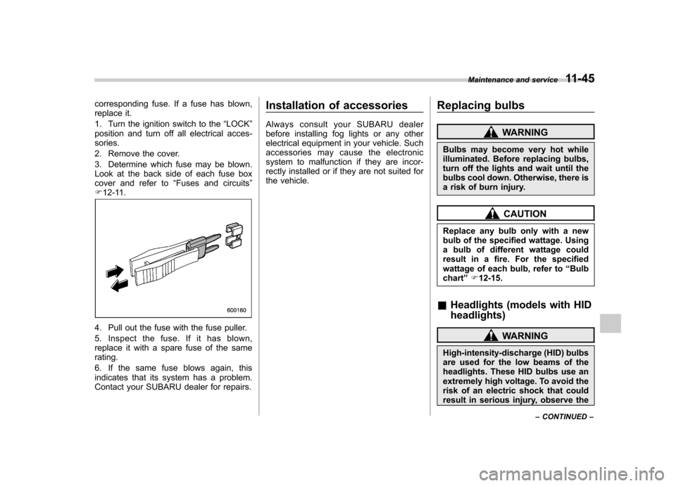
corresponding fuse. If a fuse has blown,
replace it.
1. Turn the ignition switch to the“LOCK ”
position and turn off all electrical acces- sories.
2. Remove the cover.
3. Determine which fuse may be blown.
Look at the back side of each fuse box
cover and refer to “Fuses and circuits ”
F 12-11.
4. Pull out the fuse with the fuse puller.
5. Inspect the fuse. If it has blown,
replace it with a spare fuse of the samerating.
6. If the same fuse blows again, this
indicates that its system has a problem.
Contact your SUBARU dealer for repairs. Installation of accessories
Always consult your SUBARU dealer
before installing fog lights or any other
electrical equipment in your vehicle. Such
accessories may cause the electronic
system to malfunction if they are incor-
rectly installed or if they are not suited for
the vehicle.
Replacing bulbs
WARNING
Bulbs may become very hot while
illuminated. Before replacing bulbs,
turn off the lights and wait until the
bulbs cool down. Otherwise, there is
a risk of burn injury.
CAUTION
Replace any bulb only with a new
bulb of the specified wattage. Using
a bulb of different wattage could
result in a fire. For the specified
wattage of each bulb, refer to “Bulb
chart ”F 12-15.
& Headlights (models with HID headlights)
WARNING
High-intensity-discharge (HID) bulbs
are used for the low beams of the
headlights. These HID bulbs use an
extremely high voltage. To avoid the
risk of an electric shock that could
result in serious injury, observe the Maintenance and service
11-45
– CONTINUED –
Page 385 of 438

11-46Maintenance and service
following precautions. .Do not replace any headlight
bulbs (both low beam and high
beam) by yourself.
. Do not remove/restore the head-
light assemblies by yourself.
. Do not remove any headlight-
assembly components by your-self.
For replacement, contact your
SUBARU dealer.
& Headlights (models without
HID headlights)
CAUTION
Halogen headlight bulbs become
very hot while in use. If you touch
the bulb surface with bare hands or
greasy gloves, fingerprints or
grease on the bulb surface will
develop into hot spots, causing the
bulb to break. If there are finger
prints or grease on the bulb surface,
wipe them away with a soft cloth
moistened with alcohol. NOTE .
If headlight aiming is required, con-
sult your SUBARU dealer for proper adjustment.. It may be difficult to replace the
bulbs. Have the bulbs replaced by your
SUBARU dealer if necessary. !
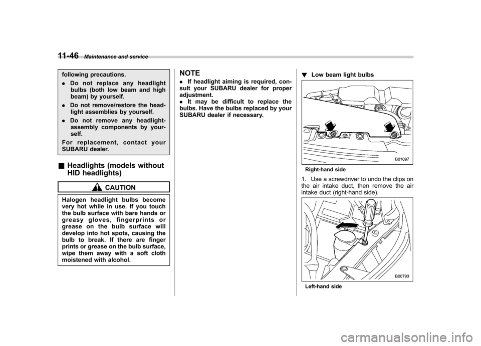
Low beam light bulbs
Right-hand side
1. Use a screwdriver to undo the clips on
the air intake duct, then remove the air
intake duct (right-hand side).
Left-hand side
Page 386 of 438

2. Use a Phillips screwdriver to remove
the secured clip of the washer tank. To
make it easy to access the bulb, move the
washer tank to the horizontal direction
(left-hand side).
3. Remove the bulb cover by turning it counterclockwise.
4. Disconnect the electrical connector
from the bulb.
5. Remove the bulb from the headlight
assembly by turning it counterclockwise.
6. Replace the bulb with a new one. At
this time, do not touch the bulb surface.7. To install the bulb to the headlight
assembly, turn it clockwise until it clicks.
8. Reconnect the electrical connector.
9. Install the bulb cover.
10. Install the air intake duct with clips
(right-hand side).
11. Set the washer tank to the original
place and secure it by clip (left-hand side). !
High beam light bulbs
Right-hand side
1. Use a screwdriver to undo the clips on
the air intake duct, then remove the air
intake duct (right-hand side). Maintenance and service
11-47
– CONTINUED –
Page 387 of 438

11-48Maintenance and service
2. Disconnect the electrical connector
from the bulb.
3. Remove the bulb from the headlight
assembly by turning it counterclockwise.
4. Replace the bulb with new one. At this
time, be careful not to touch the bulb surface. Turn the bulb clockwise until itclicks.
5. Reconnect the electrical connector.
6. Install the air intake duct with clips
(right-hand side).
& Position light
1. Turn the bulb socket counterclockwise
and pull out the socket.
2. Pull the bulb out of the socket.
3. Install a new bulb.
4. Install the bulb socket by turning it clockwise. &
Front turn signal light
It may be difficult to replace the bulbs.
Have the bulbs replaced by your SUBARU
dealer if necessary. & Rear combination lights1. Using a Phillips screwdriver, remove
the upper and lower screws that secure
the rear combination light assembly.