2012 SUBARU FORESTER change time
[x] Cancel search: change timePage 214 of 438

gistering procedure was not successful
and the mode changes to theBluetooth®
audio setting mode. NOTE
After the ignition switch is turned to the “LOCK ”position, the registered device
is not automatically connected to the
system even if the ignition switch is
turned to the “Acc ”or “ON ”position.
! Selecting device
1. Select the “SELECT AUDIO ”(type C
audio)/ “Select Audio Player ”(type D
audio) menu. If no devices are registered,“ EMPTY ”is displayed and the mode
changes to the Bluetooth
®audio setting
mode.
2. Select the “CONFIRM ”menu. If the
device is connected, “SELECTED ”is
displayed and the selecting procedure is
finished. If the device cannot be con-nected, “FAILED ”is displayed and the
selecting procedure was not successful. ! Setting passkey
1. Select the “SET PASSKEY ”menu.
After the currently set passkey is dis-
played, a new passkey can be entered.
2. Input the new passkey by operating the “TUNE/TRACK/CH ”dial. 3. Select the
“CONFIRM ”menu. The new
passkey is displayed, the passkey is
changed and the mode changes to theBluetooth
®audio setting mode.
! Deleting device
1. Select the “DELETE AUDIO ”(type C
audio)/ “Delete Audio Player ”(type D
audio) menu. If no devices are registered,“ EMPTY ”is displayed and the mode
changes to the Bluetooth
®audio setting
mode.
2. Select the “CONFIRM ”menu. “DE-
LETED ”is displayed and the mode
changes to the Bluetooth
®audio setting
mode. & Bluetooth
®audio operation
NOTE
Depending on the connected device, it
may not activate as per the following
items or not work smoothly. ! How to play back
Press the
button and select the “BT-
A ” (type C audio)/ “BT Audio ”(type D
audio) mode. ! To select a track from its beginning
Select a track in the same way as for a
CD. Refer to “To select a track from the
beginning ”F 5-24. !
Repeating
Repeating is operated in the same way as
for a CD. Refer to “Repeating ”F 5-25.
Each time you briefly press the
button (type C audio)/button (the
“ RPT ”button) (type D audio), the mode
changes in the following sequence.
! Random playback
Random playback is operated in the same
way as for a CD. Refer to “Random
playback ”F 5-26. Each time you press
and hold the
button (type C audio)/
press thebutton (the “RDM ”button)
briefly (type D audio), the mode changes
in the following sequence.
! Display selection (type C audio)
Select an item to be displayed using the
same way as for a CD. Refer to “Display
selection (type A, B and C audio) ”F 5-27.
Each time you briefly press the
Audio 5-41
– CONTINUED –
Page 216 of 438

that is used, the screen on the cell
phone may remain illuminated while
the ignition switch is in the“ON ”
position. If this occurs, turn the illumi-
nation off by adjusting the cell phonesettings. . Depending on the setting of the cell
phone, the dial lock function may be
activated after making a call. Deacti-
vate the automatic dial lock function of
the cell phone before using the Hands-
free system. . Depending on the type of cell phone
that is used, operation and the sound
volume may be different from those of
cell phones currently used. . When the ignition switch is turned to
the “LOCK ”position during a call, the
call may be disconnected or continued
on the cell phone depending on the
type of cell phone that is used. Note
that operation of the cell phone may be
necessary if the call is continued on the
cell phone. . Do not speak at the same time as the
other party during a call. If you and the
party speak at the same time, it may be
difficult for the other party to hear your
voice and vice versa. This is normal. . The receiver sound volume should
be set as low as possible. Otherwise,
the party you are calling may notice an undesirable echo sound. .
Speak clearly and loudly.
. Your voice may be difficult to be
heard by the party under the following conditions.
–Driving on a rough road.
– Driving at a high speed.
– Driving with a window open.
– When air from the ventilator
blows directly towards the micro-phone. – When the sound coming from the
ventilator is loud.– When the cell phone is too close
to the microphone.
. The sound quality may degrade due
to the influence of the cell phone that is
connected to the system or the circum-
stances of the Bluetooth network. . When another Bluetooth
®device is
simultaneously connected, noise may
be heard in the voice coming from the
hands-free phone. ! Corresponding profiles for the cell phone
. HFP (Hands Free Profile): Ver. 1.0
. OPP (Object Push Profile): Ver. 1.1 &
Certification for the Hands-
free system
CAUTION
FCC WARNING
Changes or modifications not ex-
pressly approved by the party re-
sponsible for compliance could void
the user ’s authority to operate the
equipment.
NOTE
This device complies with Part 15 of
the FCC Rules and RSS-Gen of IC
Rules. Operation is subject to the
following two conditions: (1) this de-
vice may not cause harmful interfer-
ence, and (2) this device must accept
any interference received, including
interference that may cause undesiredoperation. NOTE
This equipment has been tested and
found to comply with the limits for a
Class B digital device, pursuant to Part
15 of the FCC Rules. These limits are
designed to provide reasonable protec-
tion against harmful interference in a
residential installation. This equipment Audio
5-43
– CONTINUED –
Page 231 of 438

6-2Interior equipment
Interior lights
When leaving your vehicle, make sure the
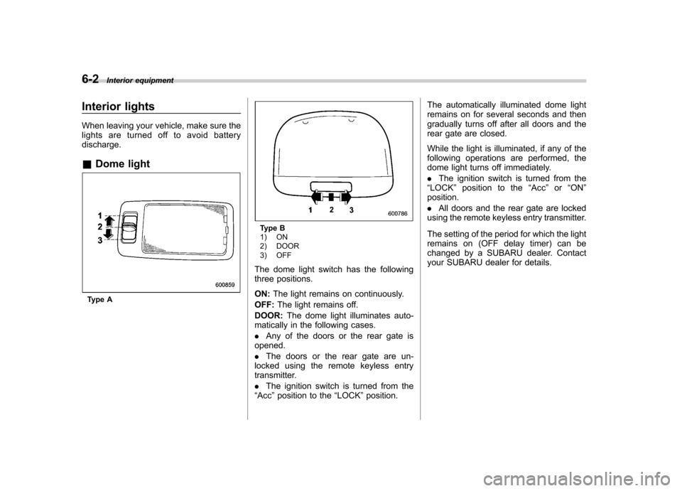
lights are turned off to avoid batterydischarge. &Dome light
Type A
Type B
1) ON
2) DOOR
3) OFF
The dome light switch has the following
three positions. ON: The light remains on continuously.
OFF: The light remains off.
DOOR: The dome light illuminates auto-
matically in the following cases. . Any of the doors or the rear gate is
opened.. The doors or the rear gate are un-
locked using the remote keyless entry
transmitter. . The ignition switch is turned from the
“ Acc ”position to the “LOCK ”position. The automatically illuminated dome light
remains on for several seconds and then
gradually turns off after all doors and the
rear gate are closed.
While the light is illuminated, if any of the
following operations are performed, the
dome light turns off immediately. .
The ignition switch is turned from the
“ LOCK ”position to the “Acc ”or “ON ”
position.. All doors and the rear gate are locked
using the remote keyless entry transmitter.
The setting of the period for which the light
remains on (OFF delay timer) can be
changed by a SUBARU dealer. Contact
your SUBARU dealer for details.
Page 233 of 438

6-4Interior equipment
illuminate when only the rear gate is opened.) .The doors are unlocked using the
remote keyless entry transmitter.. The ignition switch is turned from the
“ Acc ”position to the “LOCK ”position.
The automatically illuminated map lights
remain on for several seconds and then
gradually turn off after all doors are
closed. While the lights are on, if any of
the following operations are performed,
the map lights turn off immediately. . The ignition switch is turned from the
“ LOCK ”position to the “Acc ”or “ON ”
position.. All doors and the rear gate are locked
using the remote keyless entry transmitter.
The setting of the period for which the
lights remain on (OFF delay timer) can be
changed by a SUBARU dealer. Contact
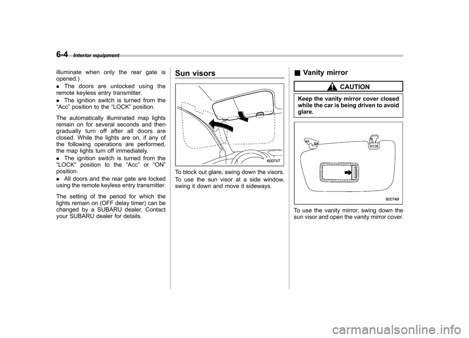
your SUBARU dealer for details. Sun visors
To block out glare, swing down the visors.
To use the sun visor at a side window,
swing it down and move it sideways.
&
Vanity mirror
CAUTION
Keep the vanity mirror cover closed
while the car is being driven to avoidglare.
To use the vanity mirror, swing down the
sun visor and open the vanity mirror cover.
Page 263 of 438

7-12Starting and operating
Pressing the brake pedal repeatedly will
toggle the feature ON or OFF each time.
7. To exit the remote transmitter and
feature programming mode, turn the igni-
tion switch to the “LOCK ”position, remove
the key from the ignition switch and test
operation of the remote transmitter(s) and
horn confirmation feature. & System maintenance
! Changing the remote control bat- teries
CAUTION
. Do not let dust, oil or water get on
or in the remote engine start
transmitter when replacing the
battery.
. Be careful not to damage the
printed circuit board in the re-
mote engine start transmitter
when replacing the battery.
. Be careful not to allow children to
touch the battery and any re-
moved parts; children could
swallow them.
. There is a danger of explosion if
an incorrect replacement battery
is used. Replace only with the
same or equivalent type of bat- tery.
. Batteries should not be exposed
to excessive heat such as sun-
shine, fire or the like.
The two 3-volt lithium batteries (modelCR-1220 ) supplied in your remote control
should last approximately 3 years, de-
pending on usage. When the batteries
begin to weaken, you will notice a
decrease in range (distance from the
vehicle that your remote control operates).
Follow the instructions below to change
the remote control batteries.1. Carefully pry the remote control halves
apart using a small flat-head screwdriver.
Page 285 of 438

7-34Starting and operating
.Push the “CANCEL ”button.
. Depress the brake pedal.
. Depress the clutch pedal (MT models).
. Shift the select lever into the “N ”
position (AT models). . Shift the shift lever into neutral position
(MT models).
The cruise control set indicator light on the
combination meter turns off when the
cruise control is canceled.To resume the cruise control after it has
been temporarily canceled, push the“ RES/ACC ”button. The vehicle will return
to the original cruising speed automati-
cally and the cruise control set indicator
light on the combination meter will illumi-nate. NOTE
If the vehicle speed has decreased
below approximately 20 mph (32
km/h), the previously set cruising
speed is canceled completely and
resetting of the cruising speed isrequired. & To turn off the cruise control
There are two ways to turn off the cruise control: .
Push the “CRUISE ”main switch button
again. . Turn the ignition switch to the “Acc ”or
“ LOCK ”position (but only when the
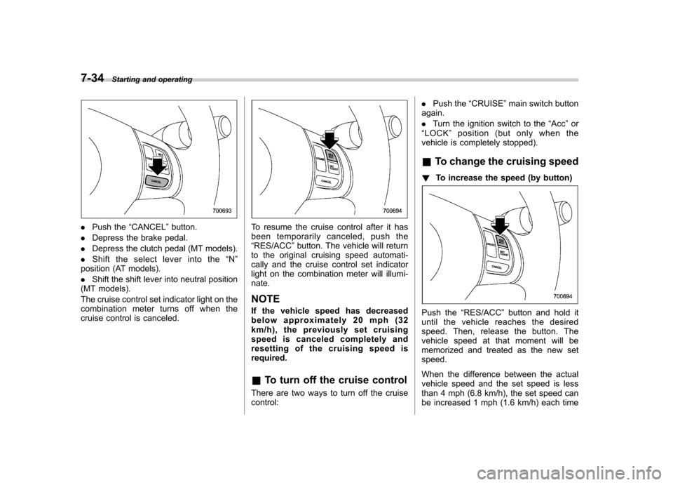
vehicle is completely stopped). & To change the cruising speed
! To increase the speed (by button)
Push the “RES/ACC ”button and hold it
until the vehicle reaches the desired
speed. Then, release the button. The
vehicle speed at that moment will be
memorized and treated as the new setspeed.
When the difference between the actual
vehicle speed and the set speed is less
than 4 mph (6.8 km/h), the set speed can
be increased 1 mph (1.6 km/h) each time
Page 306 of 438

ble.
! Total trailer weight
Total trailer weight
The total trailer weight (trailer weight plus
its cargo load) must never exceed the
maximum weight shown in the followingtable. Model Conditions
Maximum
total trailer
weight
MT models When towing a
trailer without brakes. 1,000 lbs
(453 kg)
When towing a
trailer with brakes. 2,400 lbs
(1,087 kg)
AT models When towing a
trailer without brakes. 1,000 lbs
(453 kg)
When towing a
trailer with brakes. 2,400 lbs
(1,087 kg)
When towing a
trailer on a long
uphill grade con-
tinuously for over
5 miles (8 km) with
an outside tem-
perature of 104 8F
(40 8C) or above. 1,000 lbs
(453 kg) !
Gross Vehicle Weight (GVW) and
Gross Vehicle Weight Rating(GVWR)Gross Vehicle Weight
The Gross Vehicle Weight (GVW) must
never exceed the Gross Vehicle Weight
Rating (GVWR).
Gross Vehicle Weight (GVW) is the
combined total of the weight of the vehicle,
driver, passengers, luggage, trailer hitch,
trailer tongue load and any other optional
equipment installed on your vehicle.
Therefore, the GVW changes depending
on the situation. Determine the GVW each
time before going on a trip by putting your
vehicle and trailer on a vehicle scale. Driving tips
8-19
– CONTINUED –
Page 310 of 438

!Side mirrors
After hitching a trailer to your vehicle,
check that the standard side mirrors
provide a good rearward field of view
without significant blind spots. If significant
blind spots occur with the vehicle ’s stan-
dard side mirrors, use towing mirrors that
conform with Federal, state/province and/
or other applicable regulations. ! Trailer lights
CAUTION
Direct splicing or other improper
connection of trailer lights may
damage your vehicle ’s electrical
system and cause a malfunction of
your vehicle ’s lighting system. Connection of trailer lights to your vehi-cle
’s electrical system requires modifica-
tions to the vehicle ’s lighting circuit to
increase its capacity and accommodate
wiring changes. To ensure the trailer lights
are connected properly, please consult
your SUBARU dealer. Check for proper
operation of the brake lights and turn
signal lights each time you hitch up. ! Tires
WARNING
Never tow a trailer when the tem-
porary spare tire is used. The tem-
porary spare tire is not designed to
sustain the towing load. Use of the
temporary spare tire when towing
can result in failure of the spare tire
and/or less stability of the vehicle.
Make sure that all the tires on your vehicle
are properly inflated.
The recommended cold tire pressure
under trailer towing conditions is shownin “Tires ”F12-10. Adjust the rear tire
pressure to the recommended pressure
when the tires are cold. Normal pressure
should be maintained in the front tires.
Trailer tire condition, size, load rating and
proper inflation pressure should be in accordance with the trailer manufacturer
’s
specifications.
In the event your vehicle gets a flat tire
when towing a trailer, ask a commercial
road service to repair the flat tire.
If you carry a regular size spare tire in your
vehicle or trailer as a precaution against
getting a flat tire, be sure that the spare
tire is firmly secured. & Trailer towing tips
WARNING
. Never exceed 45 mph (72 km/h)
when towing a trailer in hilly
country on hot days.
. When towing a trailer, steering,
stability, stopping distance and
braking performance will be dif-
ferent from normal operation. Forsafety ’s sake, you should employ
extra caution when towing a
trailer and you should never
drive at excessive speeds. You
should also keep the following
tips in mind: Driving tips
8-23
– CONTINUED –