2012 SUBARU FORESTER child lock
[x] Cancel search: child lockPage 95 of 438

2-10Keys and doors
&Sounding a panic alarm
A“PANIC ”button is located on the back of
the transmitter.
To activate the alarm, press the “PANIC ”
button once.
The horn will sound and the turn signal
lights will flash.
To deactivate the panic alarm, press any
button on the remote transmitter. Unless a
button on the remote is pressed, the alarm
will be deactivated after approximately 30seconds. & Selecting turn signal lights operation
When the remote keyless entry system is
used, the turn signal lights flash. However,
the turn signal lights flashing operational/ non-operational setting can be changed
by your SUBARU dealer. Contact your
SUBARU dealer for details.
& Selecting audible signal op- eration
Using an electronic chirp, the system will
give you an audible signal when the doors
lock and unlock. If desired, you may turn
the audible signal off.
Do the following to deactivate the audible
signal. You can also use the same steps
to restore the function.
1. Sit in the driver ’s seat and shut all
doors and the rear gate.
2. Hold down the UNLOCK side of the
power door locking switch.
3. While holding down the “UNLOCK ”
side of the power door locking switch, pull
the key out and re-insert it into the ignition
switch at least 6 times within 10 seconds
after step 2.
4. Open and close the driver ’s door once
within 10 seconds after step 3.
5. The turn signal lights flash 3 times to
indicate completion of the setting.
You may have the above settings done by
your SUBARU dealer. Contact your
SUBARU dealer for details. &
Replacing the battery
CAUTION
. Do not let dust, oil or water get on
or in the transmitter when repla-
cing the battery.
. Be careful not to damage the
printed circuit board in the trans-
mitter when replacing the battery.
. Be careful not to allow children to
touch the battery and any re-
moved parts; children could
swallow them.
. There is a danger of explosion if
an incorrect replacement battery
is used. Replace only with the
same or equivalent type of bat-
tery.
. Batteries should not be exposed
to excessive heat such as sun-
shine, fire or the like.
When the transmitter battery begins to get
weak, transmitter range will begin to
decrease. Replace the battery as soon
as possible.
Page 104 of 438

&Shock sensors (dealer op- tion)
The shock sensors trigger the alarm
system when they sense impacts applied
to the vehicle and when any of their
electric wires are cut. The alarm system
causes the horn to sound and the turn
signal lights to flash for a short time when
the sensed impact is weak, but it warns of
a strong impact or multiple impacts by
sounding the horn and flashing the turn
signal lights, both lasting approximately 30seconds.
If you desire, your SUBARU dealer can
connect them and set them for activation
or deactivation. NOTE . The shock sensors are not always
able to sense impacts caused by break-
ing in, and cannot sense an impact that
does not cause vibration (such as
breaking the glass using a rescuehammer).. The shock sensors may sense vi-
bration as indicated in the following
examples and trigger the alarm system.
Select the settings of the alarm system
and shock sensors appropriately de-
pending on where you usually park
your vehicle. Examples:
Vibration from a construction site
Vibration in a multistory car park
Vibration from trains
. You can have the sensitivity of the
shock sensors adjusted to your pre-
ference by your SUBARU dealer. Child safety locks
Each rear door has a child safety lock that
prevents the door from being opened even
if the inside door handle is pulled.
When the child safety lock lever is in the
lock position, the door cannot be opened
from inside regardless of the position of
the inner door handle lock lever. The door
can only be opened from the outside.
WARNING
Always turn the child safety locks to the “LOCK ”position when children
sit on the rear seat. Serious injury or
death could result if a child acciden-
tally opens the door and falls out. Keys and doors
2-19
Page 105 of 438

2-20Keys and doors
Windows
WARNING
To avoid serious personal injury
caused by entrapment, always obey
the following instructions withoutexception. . When operating the power win-
dows, be extremely careful to
prevent anyone ’s fingers, arms,
neck or head from being caught
in the window.
. Always lock the passengers ’win-
dows using the lock switch when
children are riding in the vehicle.
. Before leaving the vehicle, al-
ways remove the key from the
ignition switch for safety and
never allow an unattended child
to remain in the vehicle. Failure
to follow this procedure could
result in injury to a child operat-
ing the power window.
The power windows operate only when
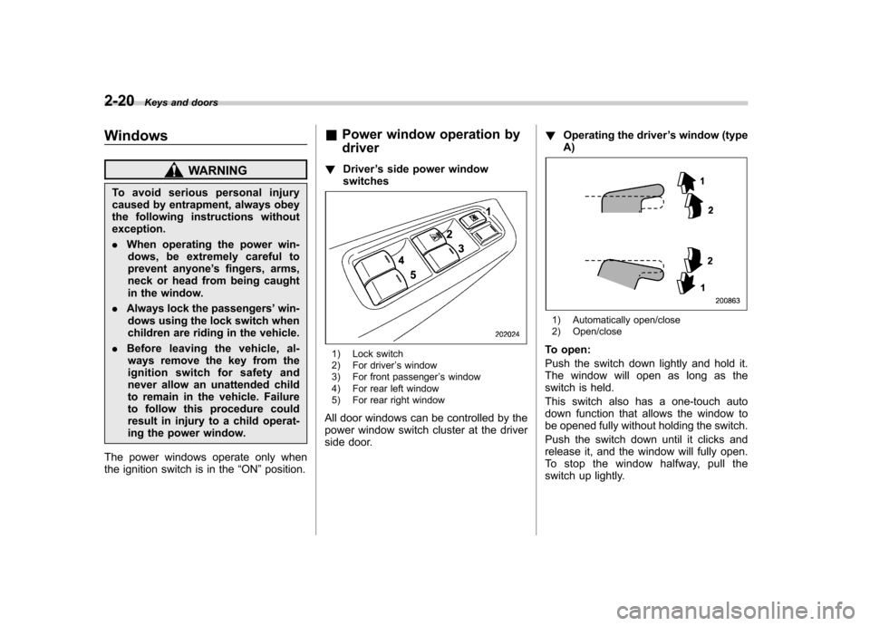
the ignition switch is in the “ON ”position. &
Power window operation by driver
! Driver ’s side power window
switches
1) Lock switch
2) For driver ’s window
3) For front passenger ’s window
4) For rear left window
5) For rear right window
All door windows can be controlled by the
power window switch cluster at the driver
side door. !
Operating the driver ’s window (type
A)
1) Automatically open/close
2) Open/close
To open:
Push the switch down lightly and hold it.
The window will open as long as the
switch is held.
This switch also has a one-touch auto
down function that allows the window to
be opened fully without holding the switch.
Push the switch down until it clicks and
release it, and the window will fully open.
To stop the window halfway, pull the
switch up lightly.
Page 109 of 438

2-24Keys and doors
.Do not attempt to shut the rear
gate while holding the inside
handle. Also avoid closing the
rear gate by pulling the inside
handle from inside the cargo
area. There is a danger of your
hand being caught and injured.
CAUTION
. Do not jam a plastic bag in or
place cellophane tape on the rear
gate stays or scratch the stays
while loading or unloading cargo.
That could cause leakage of gas
from the stays, which may result
in their inability to hold the rear
gate open.
. Be careful not to hit your head or
face on the rear gate when open-
ing or closing the rear gate and
when loading or unloading car-go.
NOTE
If the rear gate cannot be unlocked due
to a discharged vehicle battery, a
malfunction in the door locking/unlock-
ing system or other causes, you can
unlock it by manually operating the
rear gate lock release lever. For the procedure, refer to
“Rear gate –if the
rear gate cannot be opened ”F 9-18. Moonroof (if equipped)
WARNING
Never let anyone ’shands,arms,
head or any objects protrude from
the moonroof. A person could be
seriously injured if the vehicle stops
suddenly or turns sharply or if the
vehicle is involved in an accident.
To avoid serious personal injury
caused by entrapment, always obey
the following instructions withoutexception. . Before closing the moonroof,
make sure that no one ’s hands,
arms, head or other objects will
be accidentally caught in themoonroof.
. Before leaving the vehicle, al-
ways remove the key from the
ignition switch for safety and
never allow an unattended child
to remain in the vehicle. Failure
to follow this procedure could
result in injury to a child operat-
ing the moonroof.
Page 114 of 438

Ignition switch
WARNING
. Never turn the ignition switch to
“ LOCK ”while the vehicle is
being driven or towed because
that will lock the steering wheel,
preventing steering control. In
addition, when the engine is
turned off, it takes a much great-
er effort than usual to steer.
. Before leaving the vehicle, al-
ways remove the key from the
ignition switch for safety and
never allow an unattended child
to remain in the vehicle. Failure
to follow this procedure could
result in injury to a child or
others. Children could operate
the power windows, the moon-
roof or other controls or even
make the vehicle move.
CAUTION
Do not attach a large key holder or
key case to either key. If it bangs
against your knees or hands while
you are driving, it could turn the
ignition switch from the “ON ”posi- tion to the
“Acc ”or “LOCK ”posi-
tion, thereby stopping the engine.
Also, if the key is attached to a
keyholder or to a large bunch of
other keys, centrifugal force may act
on it as the vehicle moves, resulting
in unwanted turning of the ignitionswitch.
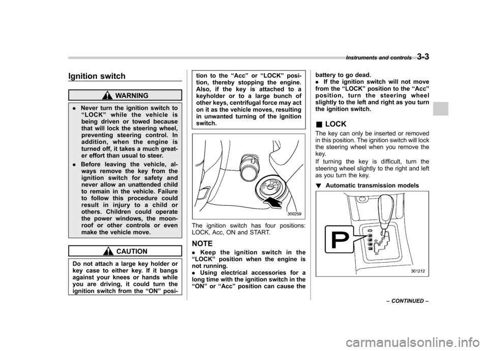
The ignition switch has four positions:
LOCK, Acc, ON and START. NOTE . Keep the ignition switch in the
“ LOCK ”position when the engine is
not running. . Using electrical accessories for a
long time with the ignition switch in the“ ON ”or “Acc ”position can cause the battery to go dead..
If the ignition switch will not move
from the “LOCK ”position to the “Acc ”
position, turn the steering wheel
slightly to the left and right as you turn
the ignition switch. & LOCK
The key can only be inserted or removed
in this position. The ignition switch will lock
the steering wheel when you remove the
key.
If turning the key is difficult, turn the
steering wheel slightly to the right and left
as you turn the key. ! Automatic transmission models
Instruments and controls 3-3
– CONTINUED –
Page 125 of 438

3-14Instruments and controls
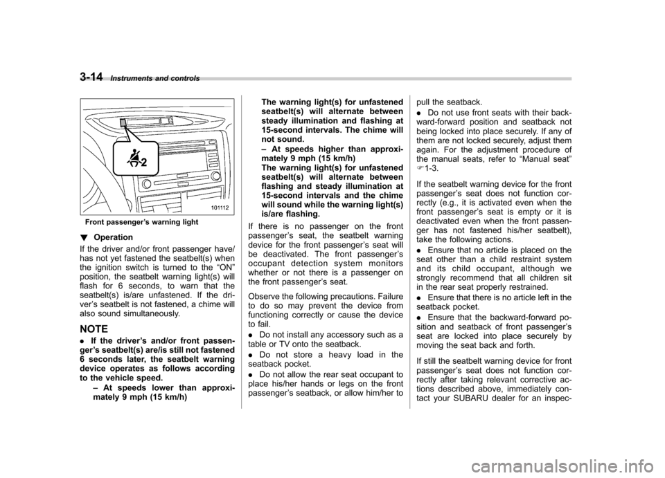
Front passenger ’s warning light
! Operation
If the driver and/or front passenger have/
has not yet fastened the seatbelt(s) when
the ignition switch is turned to the “ON ”
position, the seatbelt warning light(s) will
flash for 6 seconds, to warn that the
seatbelt(s) is/are unfastened. If the dri-ver ’s seatbelt is not fastened, a chime will
also sound simultaneously.
NOTE . If the driver ’s and/or front passen-
ger ’s seatbelt(s) are/is still not fastened
6 seconds later, the seatbelt warning
device operates as follows according
to the vehicle speed.
–At speeds lower than approxi-
mately 9 mph (15 km/h) The warning light(s) for unfastened
seatbelt(s) will alternate between
steady illumination and flashing at
15-second intervals. The chime will
not sound. –
At speeds higher than approxi-
mately 9 mph (15 km/h)
The warning light(s) for unfastened
seatbelt(s) will alternate between
flashing and steady illumination at
15-second intervals and the chime
will sound while the warning light(s)
is/are flashing.
If there is no passenger on the frontpassenger ’s seat, the seatbelt warning
device for the front passenger ’s seat will
be deactivated. The front passenger ’s
occupant detection system monitors
whether or not there is a passenger on
the front passenger ’s seat.
Observe the following precautions. Failure
to do so may prevent the device from
functioning correctly or cause the device
to fail. . Do not install any accessory such as a
table or TV onto the seatback.. Do not store a heavy load in the
seatback pocket.. Do not allow the rear seat occupant to
place his/her hands or legs on the front passenger ’s seatback, or allow him/her to pull the seatback. .
Do not use front seats with their back-
ward-forward position and seatback not
being locked into place securely. If any of
them are not locked securely, adjust them
again. For the adjustment procedure of
the manual seats, refer to “Manual seat ”
F 1-3.
If the seatbelt warning device for the frontpassenger ’s seat does not function cor-
rectly (e.g., it is activated even when the
front passenger ’s seat is empty or it is
deactivated even when the front passen-
ger has not fastened his/her seatbelt),
take the following actions. . Ensure that no article is placed on the
seat other than a child restraint system
and its child occupant, although we
strongly recommend that all children sit
in the rear seat properly restrained. . Ensure that there is no article left in the
seatback pocket.. Ensure that the backward-forward po-
sition and seatback of front passenger ’s
seat are locked into place securely by
moving the seat back and forth.
If still the seatbelt warning device for front passenger ’s seat does not function cor-
rectly after taking relevant corrective ac-
tions described above, immediately con-
tact your SUBARU dealer for an inspec-
Page 191 of 438

5-18Audio
Satellite radio operation (if equipped)
To receive satellite radio, it is necessary to
install the SUBARU genuine satellite
receiver (optional equipment) and to enter
into a contract. For details, please contact
your SUBARU dealer. &Sirius XM
TMsatellite radio
(U.S.A. only)
Sirius XM
TMis a continental U.S. based
satellite radio service, including music,
news, sports, talk and children ’s program-
ming. Sirius XM
TMprovides digital quality
audio and text information, including song
title and artist name. A service fee is
required to receive the Sirius XM
TM
service. For more information, contact
Sirius XMTMatwww.siriusxm.com.
& Satellite radio reception
Satellite radio signals are best received in
areas with a clear view of the open sky. In
areas where there are tall buildings, trees,
tunnels or other structures that may
obstruct the signal of the satellites, there
may be signal interruptions. Other circum-
stances that may result in signal loss
include driving near a wall, steep cliff, hill
or driving on the lower level of a multi- tiered road or inside of a parking garage.
To help reduce this condition, satellite
radio providers have installed ground-
based repeaters in heavily populated
areas. However, you may still experience
reception problems in some areas. !
Sirius XM
TMsatellite radio reception
tips for antenna on the windshield
(for U.S.A. only —if equipped)
For some models, the satellite radio
antenna is fixed to the upper right hand
corner of the windshield.
The Sirius XM
TMsatellite radio receiver
that is fitted to your vehicle receives the
necessary signals from two specially
designated satellites that are in a geosta-
tionary orbit over the equator. One satellite
covers the east coast and the other covers the west coast. Both of them direct their
signals north. These signals are then
relayed throughout the radio reception
area by a network of ground repeater
stations. The satellite radio signals are
transmitted as
“line of sight ”signals. The
line of sight signals can be blocked by
objects such as buildings, but the network
of repeater stations allows signal cover-
age within urban areas such as cities.
You may experience problems in receiving
Sirius XM
TMsatellite radio signals in the
following situations. . If you are driving northward in a coastal
area
Because the satellite radio antenna is
located on the windshield, the signal
comes from the south and may not be
able to reach the antenna in some
circumstances when you are driving north.
Page 263 of 438

7-12Starting and operating
Pressing the brake pedal repeatedly will
toggle the feature ON or OFF each time.
7. To exit the remote transmitter and
feature programming mode, turn the igni-
tion switch to the “LOCK ”position, remove
the key from the ignition switch and test
operation of the remote transmitter(s) and
horn confirmation feature. & System maintenance
! Changing the remote control bat- teries
CAUTION
. Do not let dust, oil or water get on
or in the remote engine start
transmitter when replacing the
battery.
. Be careful not to damage the
printed circuit board in the re-
mote engine start transmitter
when replacing the battery.
. Be careful not to allow children to
touch the battery and any re-
moved parts; children could
swallow them.
. There is a danger of explosion if
an incorrect replacement battery
is used. Replace only with the
same or equivalent type of bat- tery.
. Batteries should not be exposed
to excessive heat such as sun-
shine, fire or the like.
The two 3-volt lithium batteries (modelCR-1220 ) supplied in your remote control
should last approximately 3 years, de-
pending on usage. When the batteries
begin to weaken, you will notice a
decrease in range (distance from the
vehicle that your remote control operates).
Follow the instructions below to change
the remote control batteries.1. Carefully pry the remote control halves
apart using a small flat-head screwdriver.