2012 SUBARU FORESTER fuse box
[x] Cancel search: fuse boxPage 19 of 438

16 &Instrument panel
1) Door locks (page 2-4)
2) Outside mirror switch (page 3-44)
3) Illumination brightness control
(page 3-32)
4) Light control lever (page 3-29)
5) Combination meter (page 3-6)
6) Wiper control lever (page 3-33)
7) Hazard warning flasher switch (page 3-5)
8) Audio (page 5-1)
9) Shift lever (MT) (page 7-13)/ Select lever (AT) (page 7-15)
10) Climate control (page 4-1)
11) Cruise control (page 7-32)
12) Horn (page 3-47)
13) SRS airbag (page 1-34)
14) Tilt/telescopic steering (page 3-47)
15) Hands-free switches (page 5-42)
16) Audio control buttons (page 5-37)
17) Fuse box (page 11-44)
18) Vehicle Dynamics Control OFF switch (page 7-27)
19) Hood lock release knob (page 11-5)
20) Power windows (page 2-20)
Page 262 of 438

transmitter within a few seconds immedi-
ately following remote engine start shut-down. &Pre-heating or pre-cooling
the interior of the vehicle
Before exiting the vehicle, set the tem-
perature controls to the desired setting
and operation. After the system starts the
vehicle, the heater or air-conditioning will
activate and heat or cool the interior to
your setting. & Service mode
In service mode, the remote start function
is temporarily disabled to prevent the
system from unexpectedly starting the
engine while being serviced. ! To engage the service mode
Turn the ignition switch to the “ON ”
position, depress and hold the brake
pedal, then press and release the “
”
button on the remote control transmitter
three times. The system will pause for 1
second and then flash the turn signal
lights and honk the horn three times
indicating that the system is in service
mode. When attempting to activate the
remote start system while in service
mode, the turn signal lights will flash and
the horn will honk two times and will not start. !
To disengage the service mode
Turn the ignition switch to the “ON ”
position, depress and hold the brake
pedal, then press and release the “
”
button on the remote control transmitter
three times. The system will pause for 1
second and flash the turn signal lights 1
time indicating that the system has exited
service mode. NOTE
When taking your vehicle in for service,
it is recommended that you inform the
service personnel that your vehicle is
equipped with a remote control startsystem. & Remote transmitter program-
ming and programmable fea-
ture option
New transmitters can be programmed to
the engine starter system in the event that
remote transmitters are lost, stolen or
damaged. The remote engine start system
also has one programmable feature that
can be adjusted for user preference.
The remote engine starter system can be
programmed to either make an audible
horn chirp upon remote start activation or
not. Remote transmitter programming and feature programming can be adjusted
using the following procedure.
1. Open the driver
’s door (the driver ’s
door must remain opened throughout the
entire process).
2. Insert the key into the vehicle ’s ignition
switch and turn to the “ON ”position.
3. Locate the small black programming
button behind the fuse box cover, on the
driver ’s side left under the dashboard
panel.
4. Press and hold the black programming
button for 10 to 15 seconds. The horn will
honk and the turn signal lights will flash
three times to indicate that the system has
entered programming mode. At this point
you can proceed to either step 5 or step 6.
5. To program a remote transmitter:
press and release the “
”button on each
transmitter. The horn will honk and the
turn signal lights will flash one time to
indicate a successful transmitter learn
each time the “
”button is pressed. You
can program up to eight transmitters.
6. To toggle the Horn Confirmation chirps
ON/OFF: press and release the brake to
toggle the feature. The horn will chirp and
the turn signal lights will flash one time to
indicate Confirmation Horn Chirps are“ OFF ”. The horn will honk and the turn
signal lights will flash 2 times to indicate
Confirmation Horn Chirps are “ON ”.
Starting and operating
7-11
– CONTINUED –
Page 316 of 438
install the conventional tire as soon as possible.
Check the inflation pressure of the tem-
porary spare tire periodically to keep the
tire ready for use. The correct pressure is
60 psi (420 kPa, 4.2 kg/cm
2).
When using the temporary spare tire, note
the following. . Do not exceed 50 mph (80 km/h).
. Do not put a tire chain on the temporary
spare tire. Because of the smaller tire size,
a tire chain will not fit properly. . Do not use two or more temporary
spare tires at the same time.. Do not drive over obstacles. This tire
has a smaller diameter, so road clearance
is reduced.
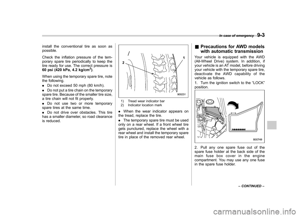
1) Tread wear indicator bar
2) Indicator location mark
. When the wear indicator appears on
the tread, replace the tire. . The temporary spare tire must be used
only on a rear wheel. If a front wheel tire
gets punctured, replace the wheel with a
rear wheel and install the temporary spare
tire in place of the removed rear wheel. &
Precautions for AWD models
with automatic transmission
Your vehicle is equipped with the AWD
(All-Wheel Drive) system. In addition, if
your vehicle is an AT model, before driving
your vehicle with the temporary spare tire,
deactivate the AWD capability of the
vehicle as follows.
1. Turn the ignition switch to the “LOCK ”
position.
2. Pull any one spare fuse out of the
spare fuse holder at the back side of the
main fuse box cover in the engine
compartment. You may use any one fuse
in the spare fuse holder. In case of emergency
9-3
– CONTINUED –
Page 317 of 438
9-4In case of emergency
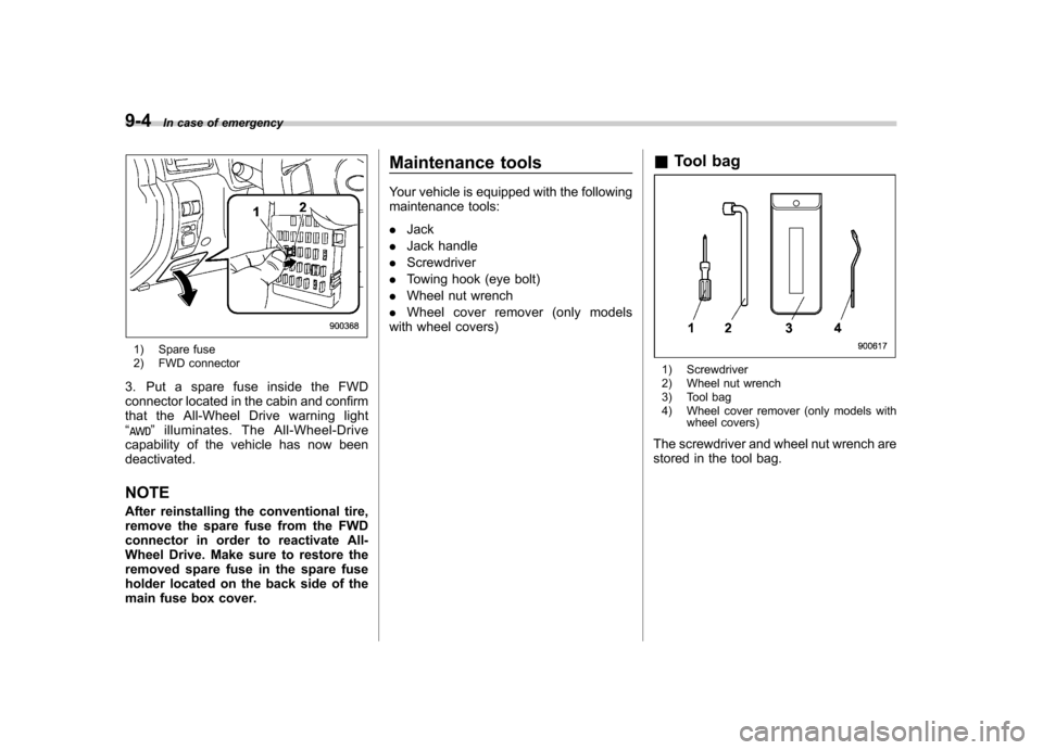
1) Spare fuse
2) FWD connector
3. Put a spare fuse inside the FWD
connector located in the cabin and confirm
that the All-Wheel Drive warning light“
” illuminates. The All-Wheel-Drive
capability of the vehicle has now been deactivated. NOTE
After reinstalling the conventional tire,
remove the spare fuse from the FWD
connector in order to reactivate All-
Wheel Drive. Make sure to restore the
removed spare fuse in the spare fuse
holder located on the back side of the
main fuse box cover. Maintenance tools
Your vehicle is equipped with the following
maintenance tools: .
Jack
. Jack handle
. Screwdriver
. Towing hook (eye bolt)
. Wheel nut wrench
. Wheel cover remover (only models
with wheel covers) &
Tool bag
1) Screwdriver
2) Wheel nut wrench
3) Tool bag
4) Wheel cover remover (only models with
wheel covers)
The screwdriver and wheel nut wrench are
stored in the tool bag.
Page 346 of 438
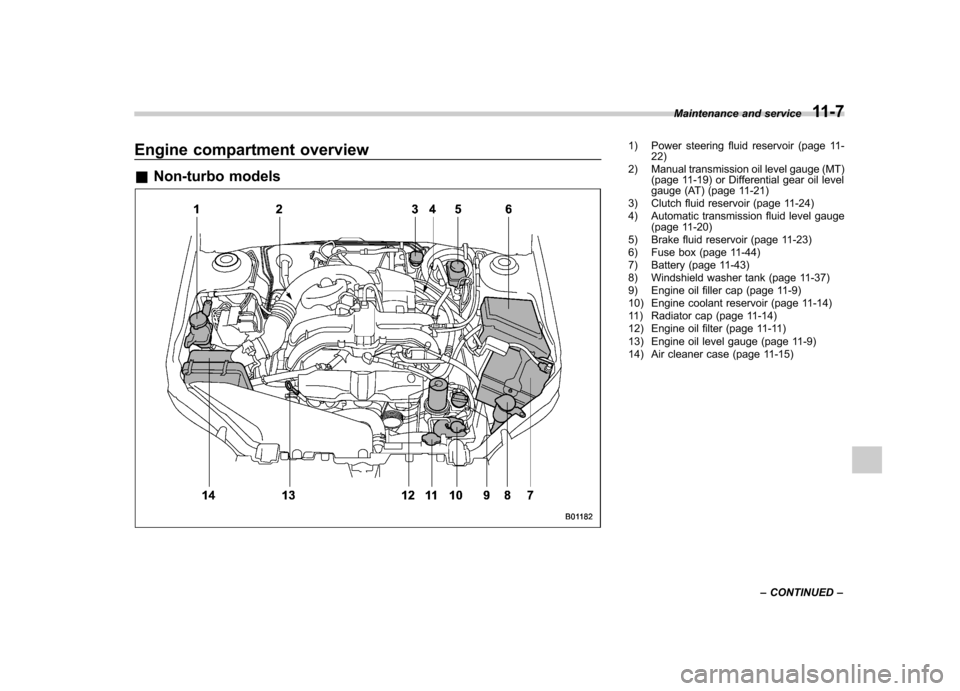
Engine compartment overview &Non-turbo models1) Power steering fluid reservoir (page 11-
22)
2) Manual transmission oil level gauge (MT) (page 11-19) or Differential gear oil level
gauge (AT) (page 11-21)
3) Clutch fluid reservoir (page 11-24)
4) Automatic transmission fluid level gauge (page 11-20)
5) Brake fluid reservoir (page 11-23)
6) Fuse box (page 11-44)
7) Battery (page 11-43)
8) Windshield washer tank (page 11-37)
9) Engine oil filler cap (page 11-9)
10) Engine coolant reservoir (page 11-14)
11) Radiator cap (page 11-14)
12) Engine oil filter (page 11-11)
13) Engine oil level gauge (page 11-9)
14) Air cleaner case (page 11-15) Maintenance and service
11-7
– CONTINUED –
Page 347 of 438
11-8Maintenance and service
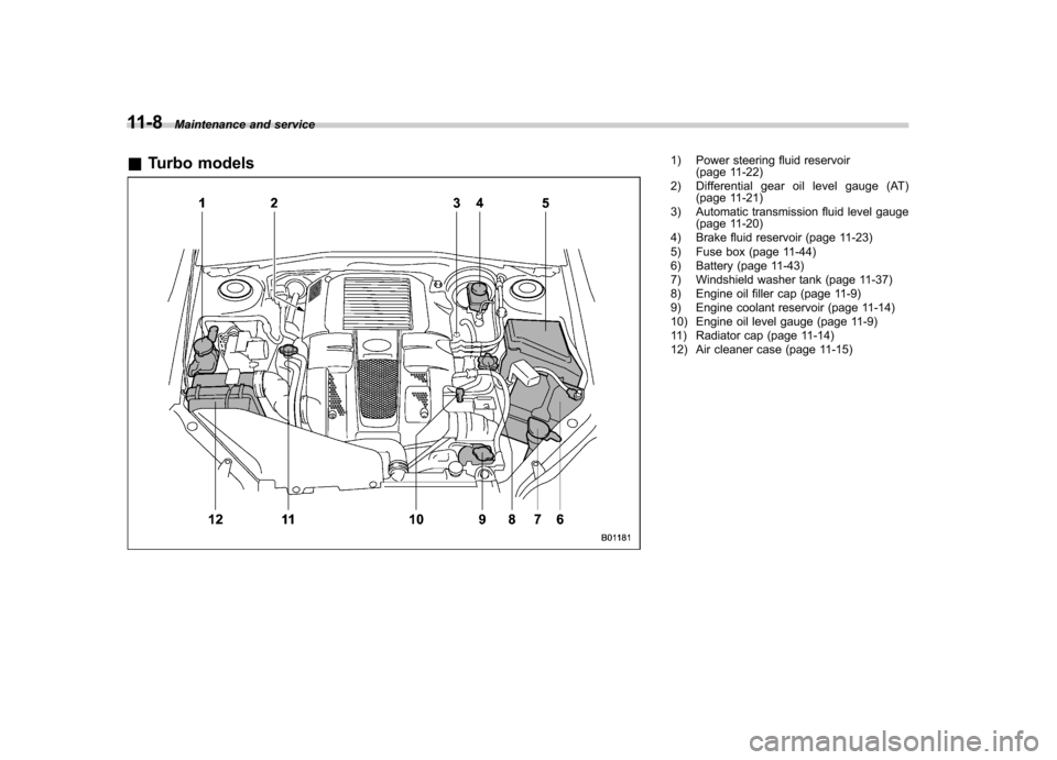
& Turbo models
1) Power steering fluid reservoir
(page 11-22)
2) Differential gear oil level gauge (AT) (page 11-21)
3) Automatic transmission fluid level gauge (page 11-20)
4) Brake fluid reservoir (page 11-23)
5) Fuse box (page 11-44)
6) Battery (page 11-43)
7) Windshield washer tank (page 11-37)
8) Engine oil filler cap (page 11-9)
9) Engine coolant reservoir (page 11-14)
10) Engine oil level gauge (page 11-9)
11) Radiator cap (page 11-14)
12) Air cleaner case (page 11-15)
Page 383 of 438

11-44Maintenance and service
Fuses
CAUTION
Never replace a fuse with one hav-
ing a higher rating or with material
other than a fuse because serious
damage or a fire could result.
The fuses are designed to melt if an
overload occurs to prevent damage to the
wiring harness and electrical equipment.
The fuses are located in two fuse boxes.
One is located under the instrument panel
behind the fuse box cover on the driver ’s
seat side. To remove the cover, pull it out.
The other one (main fuse box) is in the
engine compartment.
The spare fuses are stored in the main
fuse box cover in the engine compart-ment.
The fuse puller is stored in the main fuse
box in the engine compartment.
1) Good
2) Blown
If any lights, accessories or other electrical
controls do not operate, inspect the
Page 384 of 438
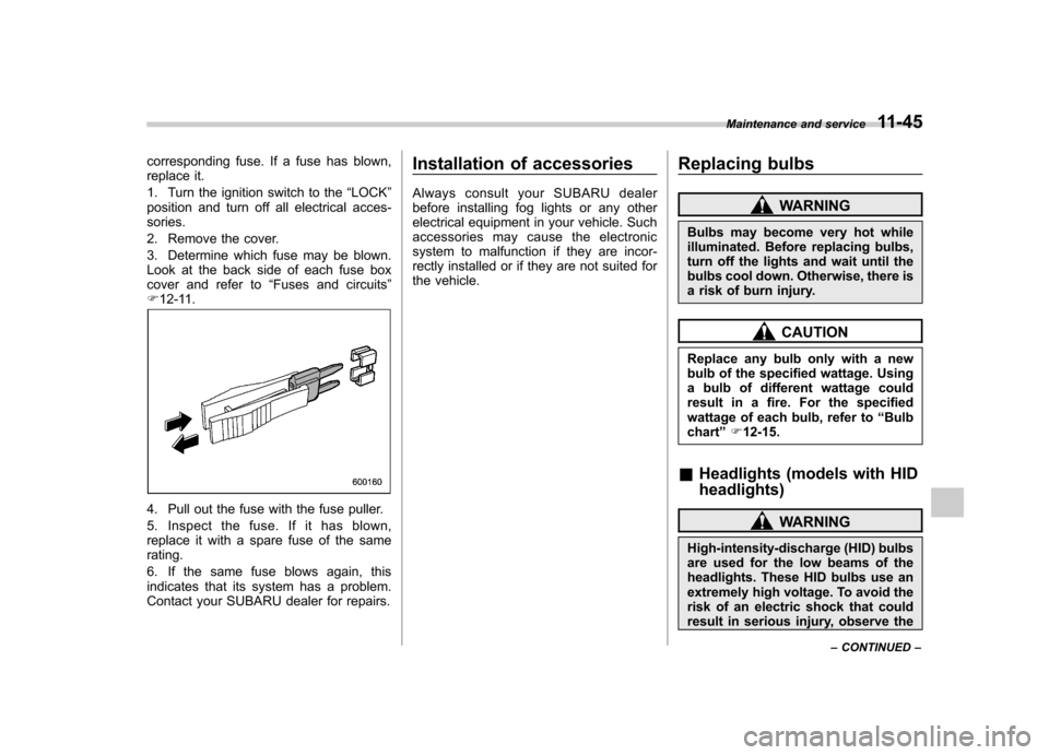
corresponding fuse. If a fuse has blown,
replace it.
1. Turn the ignition switch to the“LOCK ”
position and turn off all electrical acces- sories.
2. Remove the cover.
3. Determine which fuse may be blown.
Look at the back side of each fuse box
cover and refer to “Fuses and circuits ”
F 12-11.
4. Pull out the fuse with the fuse puller.
5. Inspect the fuse. If it has blown,
replace it with a spare fuse of the samerating.
6. If the same fuse blows again, this
indicates that its system has a problem.
Contact your SUBARU dealer for repairs. Installation of accessories
Always consult your SUBARU dealer
before installing fog lights or any other
electrical equipment in your vehicle. Such
accessories may cause the electronic
system to malfunction if they are incor-
rectly installed or if they are not suited for
the vehicle.
Replacing bulbs
WARNING
Bulbs may become very hot while
illuminated. Before replacing bulbs,
turn off the lights and wait until the
bulbs cool down. Otherwise, there is
a risk of burn injury.
CAUTION
Replace any bulb only with a new
bulb of the specified wattage. Using
a bulb of different wattage could
result in a fire. For the specified
wattage of each bulb, refer to “Bulb
chart ”F 12-15.
& Headlights (models with HID headlights)
WARNING
High-intensity-discharge (HID) bulbs
are used for the low beams of the
headlights. These HID bulbs use an
extremely high voltage. To avoid the
risk of an electric shock that could
result in serious injury, observe the Maintenance and service
11-45
– CONTINUED –