2012 SSANGYONG KORANDO belt
[x] Cancel search: beltPage 679 of 1082

05-16
Indicator
(green)
Passenger seat belt reminder ▶
Left turn signal indicator ▶
Right turn signal indicator ▶
Indicator
(red)
Indicator
(green)
Indicator
(red)
Winter mode indicator(DSL only) ▶The right turn signal indicator blinks if the light switch is pushed up to the right,
and both turn signal indicators blink if the hazard warning flasher switch is
pressed.
When the mode switch is pressed, the winter mode is selected and the
winter mode indicator comes on on the instrument cluster. The winter
mode is used to start off on a slippery road with the 2nd gear. If the switch
is pressed again, the winter mode is deactivated and system returns to
standard mode.This indicator comes on when the ignition switch is turned to the "ON"
position and goes off when the passenger's seat belt is fastened.
The left turn signal indicator blinks if the light switch is pushed down to the
left, and both turn signal indicators blink if the hazard warning flasher switch
is pressed.
Smart key warning lamp ▶
Indicator
(amber)
This lamp comes on when the uncertified transponder or smart key is
detected,
SKM system is defective or there is no smart key in the vehicle.
Page 688 of 1082

05-258010-01
Operations for power supply in SVC ▶
When the ignition switch is turned to ON position, the message "WELCOME" is displayed for 2
seconds on the DOT LCD and the seat belt reminder comes on for 4 seconds. However, if a signal
with higher priority is received, the seat belt reminder comes on only for 2 seconds to display it.
The pre-warning (system check) indicator comes on for 4 seconds and goes off 0.4 seconds after
that the ignition is switched on.
All input signals can be input 4 seconds after the pre-warning (system check) indicator starts
illuminating.
Only the symbol and DOT LCD are illuminated initially, if the SKM (Smart Key Module) or door (B-
CAN) signal is received
while B+ power is supplied.
If the ignition is switched on with the LCD illuminated, the DOT LCD and the symbol follow
the side fascia panel.
When the step 1, 2 and 3 are performed after 4 seconds, the seat belt warning lamp is deactivated in
advance.
Dial light ON condition: Lights up gradually for 2 seconds when the ignition is switched on. 1.
2.
3.
4.
5.
6.
5) Illumination & Brightness
(1) Operations for Power Supply
Page 708 of 1082

05-458010-01
Pin No.Message
Operating condition
Ambient temperature:
indicates air temperature
outside controlTRIP switch
Trip AReset: Press and hold the Trip switch
for more than 1 second
Trip BReset: Press and hold the Trip switch
for more than 1 second
Distance to empty:
indicates a distance can be
driven with the fuel remaining
controlFactory-setting mode
Average fuel consumption:
indicates average fuel
controlReset: Press and hold the Trip switch
for more than 1 second
Instant fuel consumption:
indicates fuel consumption for
a short periodsTRIP switch
Illumination brightness:
indicates tail lamp brightness
controlBrightness control: Press and hold the
Trip switch for more than 1 second
Start-up screenDisplayed for 2 seconds right after
ignition is switched on
Driver's seat belt
reminderDisplayed for 4 seconds after
'WELCOME' screen
DOT LCD message display ▶
Pin No. Message Operating condition
Page 834 of 1082

01-24
4) Basic Inspection
(1) Horn operation
Listen for the horn sound when pressing the horn pad on the steering wheel. -
(2) Brake operation
Check if there is any abnormal noise, unusually long braking distance, or uneven braking force. If the
brake warning lamp does not go out even after starting the engien or are flashing during driving,
have the brake system checked immediately.
Check the brake pipes and hoses for connection, oil leak, crack or interference after changing the
position of tires. When replacing the tires, check the brake disc for surface condition and wear.
Check the parking brake cable and brake operation. Shorten the checking interval if the parking
brake is used frequently. -
-
-
(3) Exhaust system
Be aware to any changes in sound or smell from the exhaust system. These may be caused by leak or
overheat. Have the exhaust system checked and repaired immediately.
Inspect the exhaust system including catalytic converter. Inspect all the components and body frame
near the exhaust system. -
-
(4) Tires
Unusual vibration of the steering wheel and seats or pulling to one side on the straight and level roads
may indicates the uneven tire inflation pressure or poor wheel balance. -
(5) Steering and suspension system
Inspect the front and rear suspension and the steering system for damage, looseness or missing
parts, signs of wear or lack of lubrication. Inspect the power steering line and the hoses for
connection, leak, crack and chafing. Inspect the drive axle boot and seals for damage, tear or leak.
Replace or repair the system if necessary. -
(6) Engine oil
Check the oil level when the engine is still warm and add the specified engine oil if necessary. -
(7) Coolant
Check the coolant level in the coolant reservoir, coolant conditions (contamination, foreign material),
and hoses for damage and leak. Replace or add the Ssangyong genuine coolant, if needed. -
(8) Engine drive belt
Check all drive belts on the engine for wear, crack and looseness. Retighten or replace the belt, if
needed. -
Page 985 of 1082

12-8
Installation of steering
gear box and pipeInstallation of pipe
Installation of reservoir and hoseInstallation of power steering pump
and pipe
2. SYSTEM LAYOUT
The steering pump is driven by the engine power through a belt. This pump circulates the power steering
oil from the reservoir -> steering pump -> oil supply pipe -> steering gear box -> oil return pipe ->
reservoir to perform steering operations.
Return pipe
Supply pipe
Page 989 of 1082

13-6
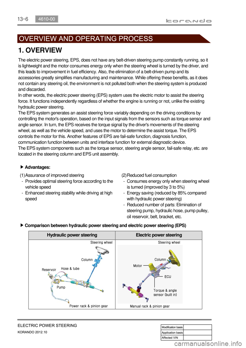
Hydraulic power steering Electric power steering
1. OVERVIEW
The electric power steering, EPS, does not have any belt-driven steering pump constantly running, so it
is lightweight and the motor consumes energy only when the steering wheel is turned by the driver, and
this leads to improvement in fuel efficiency. Also, the elimination of a belt-driven pump and its
accessories greatly simplifies manufacturing and maintenance. While offering these benefits, as it does
not contain any steering oil, the environment is not polluted both when the steering system is produced
and discarded.
In other words, the electric power steering (EPS) system uses the electric motor to assist the steering
force. It functions independently regardless of whether the engine is running or not, unlike the existing
hydraulic power steering.
The EPS system generates an assist steering force variably depending on the driving conditions by
controlling the motor's operation, based on the input signals from the sensors such as torque sensor and
angle sensor. In turn, the EPS receives the torque signal by the driver's movements of the steering
wheel, as well as the vehicle speed, and uses the motor to determine the assist torque. The EPS
controls the motor for this. Another features of EPS are fail-safe function, diagnosis function,
communication function between units and interface function for external diagnostic device.
The EPS system components such as the torque sensor, steering angle sensor, fail-safe relay, etc. are
located in the steering column and EPS unit assembly.
Advantages: ▶
Assurance of improved steering
Provides optimal steering force according to the
vehicle speed
Enhanced steering stability while driving at high
speed (1)
-
-Reduced fuel consumption
Consumes energy only when steering wheel
is turned (improved by 3 to 5%)
Energy saving (reduced by 85% compared
with hydraulic power steering)
Reduced number of parts: Elimination of
steering pump, hydraulic hose, pump pulley,
oil reservoir, belt, bracket, etc. (2)
-
-
-
Comparison between hydraulic power steering and electric power steering (EPS) ▶
Page 992 of 1082

14-4
1. OVERVIEW
A radial tire uses a cord angle of 90 degrees. That is, the cord material runs in a radial or direct line from
one bead to the other across the tread. In addition, a radial tire has a belt overwrap under the tread
surface to provide greater structural stability. The belt overwrap of a radial tire distortion while the radial
structure enables high speed driving.
Tire supports the weight of the vehicle, reduces the impact from the road and at the same time,
transmits the power to propel, brake and steer on the road. It also functions to maintain a
<009d008c008f0090008a0093008c02c5009a004700940096009d008c0094008c0095009b0055004700700095004700960099008b008c00990047009b00960047008a0096009400970093008c009b008c0047009a009c008a008f0047009b0088009a009200
9a0053004700880047009b00900099008c00470094009c009a>t be structured to be a resilient
vessel of air.
There is wear limit mark on the tire, which protrudes as a strip shape located approximately 1.6 mm from
<009b008f008c0047008e009900960096009d008c004700890096009b009b0096009400550047007b008f0090009a0047009e008c0088009900470093009000940090009b0047009400880099009200470090009a004700950096009b0047009a008c008c00
950047008d0099009600940047009b008f008c00470096009c>tside so there is additional "▲"
mark on the shoulder to let the driver find the wear mark easily. To measure the tire groove depth,
measure at any point other than the point which has a wear limit mark.
The tire is worn unevenly according to the driver's driving habit, improper servicing, low tire inflation
pressure, changed tire location, etc.
1) Structure of Tire
Tread
This thick layer of rubber provides the interface
between the tire and the road. Wear-resistant
rubber is used to protect the carcass and belt
against fractures and impacts and to deliver a
long driving life.
Shoulder
Located between the tread and sidewall, the
shoulder rubber is the thickest so that the design
must allow for the easy diffusion of heat
generated within the tire while driving.
Sidewall
The part between the shoulder and bead, the
flexible sidewall protects the carcass and
enhances the ride. A tire’s type, size,
structure, pattern, manufacturing company,
product name and various characters are
indicated here. Bead
The bead attaches the tire to the rim and wraps
the end of the cord fabric. Comprised of the bead
wire, core, flipper and other parts, the bead is
generally designed to be slightly tight around the
rim so that in the case of a sudden drop in inflation
pressure, the tire will not fall off the rim.
Carcass
As the most important framework of a tire, the
entire inner layer of cord fabric is called the
carcass. The carcass acts to support air pressure,
vertical load and absorb shocks.
Valve
Belt
Bead core
Page 1019 of 1082

02-38810-00
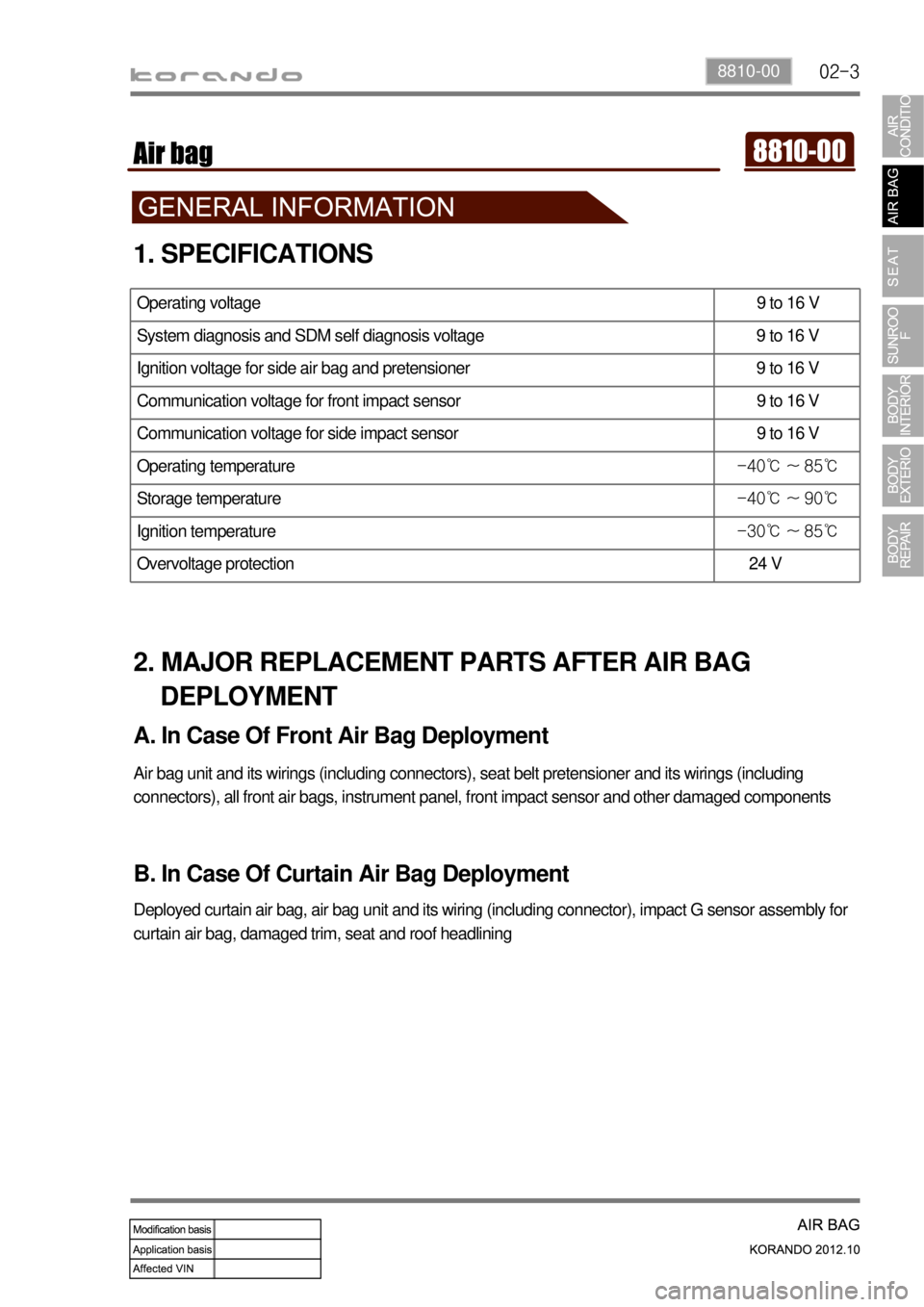
1. SPECIFICATIONS
Operating voltage 9 to 16 V
System diagnosis and SDM self diagnosis voltage 9 to 16 V
Ignition voltage for side air bag and pretensioner 9 to 16 V
Communication voltage for front impact sensor 9 to 16 V
Communication voltage for side impact sensor 9 to 16 V
Operating temperature -40℃ ~ 85℃
Storage temperature -40℃ ~ 90℃
Ignition temperature -30℃ ~ 85℃
Overvoltage protection 24 V
2. MAJOR REPLACEMENT PARTS AFTER AIR BAG
DEPLOYMENT
A. In Case Of Front Air Bag Deployment
Air bag unit and its wirings (including connectors), seat belt pretensioner and its wirings (including
connectors), all front air bags, instrument panel, front impact sensor and other damaged components
B. In Case Of Curtain Air Bag Deployment
Deployed curtain air bag, air bag unit and its wiring (including connector), impact G sensor assembly for
curtain air bag, damaged trim, seat and roof headlining