Page 901 of 1082
04-50000-00
1. OVERVIEW
The hydraulic clutch transmits the force required to operate the clutch pedal to the concentric slave
cylinder fitted to the clutch housing as a hydraulic pressure.
(The hydraulic pressure is transmitted in the following order: Clutch pedal - Clutch master cylinder -
Clutch pipe - Clutch damper - Clutch pipe and hose - Concentric slave cylinder - Pressure plate -
Flywheel.)
If a driver depress the clutch pedal, the hydraulic pressure is generated in the master cylinder. It is
transmitted to the concentric slave cylinder through the pipe, resulting in the cylinder being forced out. At
this time, the clutch disc is forced against the cylinder by pushing the cover. This, in turn, remove the
flywheel from the pressure plate. As a consequence, the power from the engine will be cut off and the
gear change can be carried out.
Page 903 of 1082

04-70000-00
Operating Elements ▶
The clutch "release" system consists of the clutch pedal and clutch release cylinder.
This system directly releases the clutch by using hydraulic pressure while the conventional clutch system
releases the clutch by using release lever and release fork. This system provides higher efficiency than
conventional clutch system, and its durability is superior.
Clutch master cylinder (mounted on clutch pedal)
Concentric slave cylinder pipe (mounted inside of transmission) -
-Driving elements ▶
The driving elements consist of two flat surfaces machined to a smooth finish.
One of these is the rear face of the engine flywheel and the other is the clutch pressure plate. The clutch
pressure plate is fitted into a clutch steel cover, which is bolted to the flywheel.
Driven elements ▶
The driven element is the clutch disc with a splined hub which is free to slide lengthwise along the splines
of the input shaft.
The driving and driven elements are held in contact by spring pressure. This pressure is exerted by a
diaphragm spring in the clutch cover pressure plate assembly.
2) Overview
Page 905 of 1082
04-90000-00
3. DUAL MASS FLYWHEEL (DMF)
The dual mass flywheel (DMF) is of having a mass divided into two halves.
While one mass is connected to the engine crankshaft, which is affected by the mass moment of inertia
of the engine, the other mass is affected by one of the transmission.
The divided dual masses are connected to the coil spring and damping system internally.
The DMF has the following benefits: ▶
Reducing fuel consumption by lowering engine speed
Reducing rattling noise and vehicle vibration in all driving ranges
Reducing synchronization wear
Facilitating gear change
Protecting power train parts by preventing excessive load from being delivered -
-
-
-
-
Primary flywheel
Secondary flywheel
Arc damper spring
Torque limiter
Ring gear 1.
2.
3.
4.
5.
Page 915 of 1082
07-50000-00
2. SYSTEM LAYOUT
1) Components
(1) PTU (Power Transfer Unit)
<007b008f008c004700970096009e008c00990047009b009900880095009a008d008c00990047009c00950090009b0047009000950047009b008f008c0047008d009900960095009b0047009e008f008c008c00930047008b00990090009d008c0047009400
96008b008c00930047008a008f00880095008e008c009a0047>the angle of engine torque to 90°
and transfer it to E-coupling to distribute the torque to rear wheels.
(2) E-Coupling (Electronic Coupling)
E-Coupling transfer the engine torque from PTU to rear axle and controls to distribute it between front
wheels and rear wheels.
(3) E-Coupling Control Unit (ECU)
E-Coupling controls the current (clutch engagement force) of EMCD in E-Coupling according to CAN
signals (wheel speed, engine torque, pedal position, ABS/ESP signals).
* EMCD: Electro-Magnetic Control Device PTU assemblyE-coupling control unit
(located on the floor under driver seat)E-coupling
Page 958 of 1082
11-6
1. OVERVIEW
The ESP (Electronic Stability Program) has been developed to help a driver avoid danger of losing
control of the vehicle stability due to understeer or oversteer during cornering. The yaw rate sensor,
lateral sensor and longitudinal sensor in the sensor cluster and the steering wheel angle sensor under
the steering column detect the vehicle conditions when the inner or outer wheels are spinning during
oversteer, understeer or cornering. The ESP ECU controls against oversteer or understeer during
cornering by controlling the vehicle stability using input values from these sensors and applying the
braking force to the corresponding wheels independently. The system also controls the engine power
right before the wheel spin synchronized to decelerate the vehicle automatically in order to maintain the
vehicle stable during cornering.
Page 960 of 1082

11-8
3. PRECAUTIONS
The warning lamp flashes and warning beep sounds when the ESP is operating
When the ESP operates during vehicle movement, the ESP warning lamp on the instrument panel
flashes and beep comes on every 0.1 second. The ESP system is only a supplementary device for
comfortable driving. When the vehicle exceeds its physical limits, it cannot be controlled.
Do not rely on the system. Keep on the safe driving.
Feeling when ESP is working
When the ESP system activates, the feeling can be different depending on vehicle driving conditions.
For example, you will feel differently when the ESP system is activated during the ABS is operating
with the brakes applied and when the brakes are not applied on a curve.
If the ESP system operates when the brake is applied, the brake pressure will be increased on the
corresponding wheel which already has braking pressure for the ESP controls.
ARP Operation
During the ARP operation, vehicle safety (rollover prevention) takes the first priority and thus,
stronger engine control is in effect. Consequently, the vehicle speed decreases rapidly, so the driver
must take caution for the vehicle may drift away from the lane.
Noise and vibration that driver feels when ESP system is operating
The ESP system may transfer noise and vibration to the driver due to the pressure changes caused
by the motor and valve operations in a very short period of time. And, keep in mind that the output
and vehicle speed could be decreased without rpm increase due to the ASR function that controls
the engine power.
Page 964 of 1082

11-12
2) Operation of ESP System
The ESP (Electronic Stability Program) has been developed to help a driver avoid danger of losing
control of the vehicle stability due to understeer or oversteer during cornering. The yaw rate sensor,
lateral sensor and longitudinal sensor in the sensor cluster and the steering wheel angle sensor under
the steering column detect the vehicle conditions when the inner or outer wheels are spinning during
oversteer, understeer or cornering. The ESP ECU controls against oversteer or understeer during
cornering by controlling the vehicle stability using input values from these sensors and applying the
braking force to the corresponding wheels independently. The system also controls the engine power
right before the wheel spin synchronized with the ASR function to decelerate the vehicle automatically in
order to maintain the vehicle stable during cornering.
(1) Under steering
What is understeering? ▶
Understeer is a term for a condition in which the steering wheel is steered to a certain angle during driving
and the front tires slip toward the reverse direction of the desired direction. Generally, vehicles are
designed to have understeer. It is because that the vehicle can return back to inside of cornering line
when the steering wheel is steered toward the inside even when the front wheels are slipped outward.
As the centrifugal force increases, the tires can easily lose the traction and the vehicle tends to slip
outward when the curve angle gets bigger and the speed increases.
Page 968 of 1082

11-16
5) ARP (Active Roll-Over Protection)
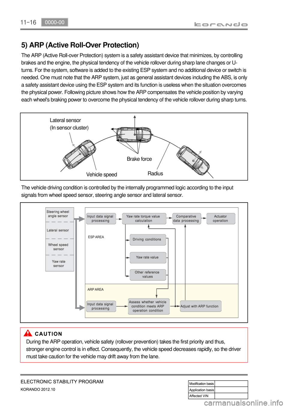
The ARP (Active Roll-over Protection) system is a safety assistant device that minimizes, by controlling
brakes and the engine, the physical tendency of the vehicle rollover during sharp lane changes or U-
turns. For the system, software is added to the existing ESP system and no additional device or switch is
needed. One must note that the ARP system, just as general assistant devices including the ABS, is only
a safety assistant device using the ESP system and its function is useless when the situation overcomes
the physical power. Following picture shows how the ARP compensates the vehicle position by varying
each wheel's braking power to overcome the physical tendency of the vehicle rollover during sharp turns.
Lateral sensor
(In sensor cluster)
Vehicle speedBrake force
Radius
The vehicle driving condition is controlled by the internally programmed logic according to the input
signals from wheel speed sensor, steering angle sensor and lateral sensor.
During the ARP operation, vehicle safety (rollover prevention) takes the first priority and thus,
stronger engine control is in effect. Consequently, the vehicle speed decreases rapidly, so the driver
must take caution for the vehicle may drift away from the lane.