2012 SSANGYONG KORANDO oil pressure
[x] Cancel search: oil pressurePage 202 of 1082

07-50000-00
1. SYSTEM DESCRIPTION
1) Overview
The lubrication system supplies oil to each lubrication section to prevent friction and wear and to remove
heat from the friction part. As the engine runs, frictional heat is generated on each lubrication section. If
this condition persists, the bearing can be burned and stuck.
In other words, it creates an oil film on each sliding surface to convert solid friction to liquid friction in
order to minimize wear and prevent temperature increasing on the friction part.
For the D20DTF engine with no oil pressure switch, the engine ECU receives the low engine oil level
signal from the oil level sensor and communicates with the instrument cluster through the CAN
communication to turn on the warning lamp.
2) Component
Oil level sensorEngine oil dipstick
Oil panOil pumpOil filter module
Oil cooler
Page 205 of 1082

07-8
3. LUBRICATION
1)Anti-friction
The oil makes a thin film on the surface of sliding components to reduce the wear due to friction.
2)Cooling
The friction makes the heat on the components. The oil absorbs the heat and radiates it or cools it down.
3) Sealing
The piston ring on the piston seals the cylinder. The oil gets into the clearance in piston ring to secure
the sealing for compression pressure and combustion gas.
4) Anti-corrosion
The oil generates the thin film on the surface of components to prevent the material from contacting with
air, water and corrosive gas.
5) Cleaning
The oil transfers the residue of material due to friction, oxidized substance, and carbonized substance
while circulating in the engine by oil pump.
Page 283 of 1082

15-70000-00
Fuel rail
pres.sensor
Differential
pressure
sensor
Swirl valve posi.
sensor
Meter cluster
Coolant temp.
sensorE-EGR valve
posi. sensor
Oxygen
sensor
Exhaust gas
temp. sensor
HFM sensor
(2) Components for ECU Input
Crankshaft posi.
sensorAccel. pedal
posi. sensorThrottle
posi.sensor
Knock sensor
T-MAP sensor
Camshaft posi.
sensor
CAN
- ABS&ESP
- GCU
- Meter cluster
- TCU
- BCM
- Refrigerant pressure sensor
- Clutch pedal signal
- Blower switch signal
- Brake pedal signal
Oil level sensor
Page 285 of 1082

15-90000-00
2) ECU Control
(1) Function
a. ECU Function
ECU receives and analyzes signals from various sensors and then modifies those signals into
permissible voltage levels and analyzes to control respective actuators.
ECU microprocessor calculates injection period and injection timing proper for engine piston speed and
crankshaft angle based on input data and stored specific map to control the engine power and emission
gas.
Output signal of the ECU microprocessor drives pressure control valve to control the rail pressure and
activates injector solenoid valve to control the fuel injection period and injection timing; so controls
various actuators in response to engine changes. Auxiliary function of ECU has adopted to reduce
emission gas, improve fuel economy and enhance safety, comforts and conveniences. For example,
there are EGR, booster pressure control, autocruise (export only) and immobilizer and adopted CAN
communication to exchange data among electrical systems (automatic T/M and brake system) in the
vehicle fluently. And Scanner can be used to diagnose vehicle status and defectives.
<00760097008c00990088009b00900095008e0047009b008c00940097008c00990088009b009c0099008c0047009900880095008e008c00470096008d0047006c006a007c00470090009a0047009500960099009400880093009300a000470054005b005700
47009b009600470052005f005c00b6006a004700880095008b> protected from factors like oil,
water and electromagnetism and there should be no mechanical shocks.
To control the fuel volume precisely under repeated injections, high current should be applied instantly
so there is injector drive circuit in the ECU to generate necessary current during injector drive stages.
Current control circuit divides current applying time (injection time) into full-in-current-phase and hold-
current-phase and then the injectors should work very correctly under every working condition.
b. Control Function
Controls by operating stages
To make optimum combustion under every operating stage, ECU should calculate proper injection
volume in each stage by considering various factors.
Starting injection volume control
During initial starting, injecting fuel volume will be calculated by function of temperature and engine
cranking speed. Starting injection continues from when the ignition switch is turned to ignition
position to till the engine reaches to allowable minimum speed.
Driving mode control
If the vehicle runs normally, fuel injection volume will be calculated by accelerator pedal travel and
engine rpm and the drive map will be used to match the drivers inputs with optimum engine power. -
-
-
Page 310 of 1082

15-34
Coolant temp.
sensor
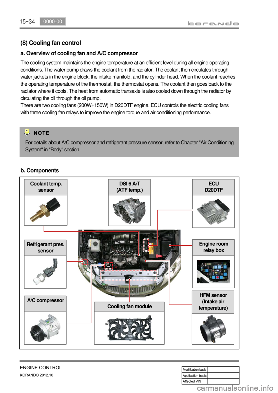
(8) Cooling fan control
a. Overview of cooling fan and A/C compressor
The cooling system maintains the engine temperature at an efficient level during all engine operating
conditions. The water pump draws the coolant from the radiator. The coolant then circulates through
water jackets in the engine block, the intake manifold, and the cylinder head. When the coolant reaches
the operating temperature of the thermostat, the thermostat opens. The coolant then goes back to the
radiator where it cools. The heat from automatic transaxle is also cooled down through the radiator by
circulating the oil through the oil pump.
There are two cooling fans (200W+150W) in D20DTF engine. ECU controls the electric cooling fans
with three cooling fan relays to improve the engine torque and air conditioning performance.
For details about A/C compressor and refrigerant pressure sensor, refer to Chapter "Air Conditioning
System" in "Body" section.
b. Components
Refrigerant pres.
sensor
A/C compressor
ECU
D20DTF DSI 6 A/T
(ATF temp.)
Cooling fan module
HFM sensor
(Intake air
temperature)
Engine room
relay box
Page 329 of 1082

01-50000-00
Right side view ▶
Left side view ▶
Rear oxygen sensor connector
Front oxygen sensor connector
Exhaust manifoldHeat protector
Front oxygen sensor
WCC complete
Crankshaft pulley
Oil pan drain plug
Rear oxygen sensor
Coolant outlet port
Injector assembly
Fuel rail
T-MAP sensor Purge control solenoid valve
Electronic throttle body
VIS solenoid valve
Oil dipstick gauge
Oil filter assembly
Thermostat assembly
Oil pressure sensor
Page 332 of 1082

01-8
4) Basic Inspection
(1) Horn operation
Listen for the horn sound when pressing the horn pad on the steering wheel. -
(2) Brake operation
Check if there is any abnormal noise, unusually long braking distance, or uneven braking force. If the
brake warning lamp does not go out even after starting the engien or are flashing during driving,
have the brake system checked immediately.
Check the brake pipes and hoses for connection, oil leak, crack or interference after changing the
position of tires. When replacing the tires, check the brake disc for surface condition and wear.
Check the parking brake cable and brake operation. Shorten the checking interval if the parking
brake is used frequently. -
-
-
(3) Exhaust system
Be aware to any changes in sound or smell from the exhaust system. These may be caused by leak or
overheat. Have the exhaust system checked and repaired immediately.
Inspect the exhaust system including catalytic converter. Inspect all the components and body frame
near the exhaust system. -
-
(4) Tires
Unusual vibration of the steering wheel and seats or pulling to one side on the straight and level roads
may indicates the uneven tire inflation pressure or poor wheel balance. -
(5) Steering and suspension system
Inspect the front and rear suspension and the steering system for damage, looseness or missing
parts, signs of wear or lack of lubrication. Inspect the power steering line and the hoses for
connection, leak, crack and chafing. Inspect the drive axle boot and seals for damage, tear or leak.
Replace or repair the system if necessary. -
(6) Engine oil
Check the oil level when the engine is still warm and add the specified engine oil if necessary. -
(7) Coolant
Check the coolant level in the coolant reservoir, coolant conditions (contamination, foreign material),
and hoses for damage and leak. Replace or add the Ssangyong genuine coolant, if needed. -
(8) Engine drive belt
Check all drive belts on the engine for wear, crack and looseness. Retighten or replace the belt, if
needed. -
Page 333 of 1082

01-90000-00
5) Guidelines on Engine Service
(1) Cautions before service works
Make sure to disconnect the negative (-) cable from the battery to prevent any damage to electric
systems.
Make sure to clean the working area and to prepare the necessary tools before service works.
Always place the ignition switch to OFF position if not required. Otherwise, there could be unexpected
damage to electric devices or personal injuries due to short-circuit.
To prevent the foreign material from entering into the fuel injection system, completely seal the inlets o
f
HP pump, fuel hoses and high pressure pipes.
To remoev the engine, use the dedicated equipments such as engine jack, transmission jack, engine
stand and engine crane. -
-
-
-
-
(2) Engine and accessories
When disassembling the engine, related parts (bolts, gaskets, etc.) should be stored as a set.
Clean the components completely with engine oil before assembling if needed.
Fully drain the engine oil, coolant and fuel from the vehicle and seal the inlets with the plugs before
removing the engine.
All the interference should be eliminated before removing the engine. -
-
-
- To prevent the personal injuries and vehicle damages that can be caused by mistakes during service
and to provide the optimized performance and safety after service works, the service technicials must
keep the basic cautions and service guidelines below. These could be easily forgotten during service
works.
Engine has a lot of precise components. The specified tightening torque and correct procedures should
be kept during service works. And, the working area is always clean and well prepared.
To prevent any damage to electric systems, make sure to disconnect the negative (-) cable from the
battery and place the ignition switch to OFF position before servicing.
Use only the specified parts with same ratings when replacing the electric devices. Check the
grounds and connections for looseness. -
-
(3) Electric devices
Extraordinary care should be taken when servicing the electric systems. Currently, the engine uses a lot
of electric devices. Short circuit and poor contact may cause the low engine performance, incomplete
combustion and other abnormalities.
When working with the fuel or oil systems in enclosed area, always keep the working area well-
ventilated and never allow anybody to smoke.
Gaskets and seals on the fuel and oil systems should be replaced with new ones. All bolts and nuts
should be tightened as specified.
Make sure to check the connections for leak after installation. -
-
-
(4) Fuel and lubrication system