2012 SSANGYONG KORANDO change time
[x] Cancel search: change timePage 736 of 1082

06-258510-00
SVC class instrument cluster
TRIP A TRIP B
(3) Trip switch
Whenever pressing this button, the information is displayed in the following order: Odometer, Trip A, Trip
B, Distance to empty, Average fuel consumption, Instant fuel consumption, Illumination level, Ambient air
temperature (for STD); Trip A, Trip B, Distance to empty, Average fuel consumption, Instant fuel
consumption, Illumination level, Ambient air temperature (for SVC). Press and hold (for more than 1 sec)
this button to initialize (reset) Trip A/Trip B and average fuel consumption, adjust illumination level or
change the unit of temperature.
Description ▶
The factory setting is DTE mode. ※ Display
Mode
SwitchDetecting
timeFunction
Briefly
and holdBelow 1
second
(60 to
980 ms)STD- Mode change
(Odo→Trip A→Trip B→DTE
<00470047004702e70068009d008c00990088008e008c0047008d009c008c00930047008a00960095009a009c00940097009b00900096009502e700700095009a009b00880095009b0047008d009c008c00930047008a00960095009a009c00940097009b00
9000960095>
→Illumination level→Ambient air temperature)
SVC- Mode change
(Trip A→Trip B→DTE→Average fuel consumption
→Instant fuel consumption→Illumination level
→Ambient air temperature)
Press
and holdOver 1
seconds- Reset
(Trip A, B, average fuel consumption)
- Change
<004700470047004f007000930093009c0094009000950088009b00900096009500470093008c009d008c00930047004f005d0047009b009600470058005000530047009b008c00940097008c00990088009b009c0099008c0047009c00950090009b004700
4f0b4502e90d9100500050>
Not
pressOver 3
seconds- Mode change
<004700470047004f007000930093009c0094009000950088009b00900096009500470093008c009d008c009302e70068009400890090008c0095009b00470088009000990047009b008c00940097008c00990088009b009c0099008c02e70076008b009600
50>
STD class instrument cluster
TRIP A TRIP B
Page 763 of 1082

07-10
(5) Auto light (LIN)
The auto light sensor unit is installed to the back side of the ECM mirror located upper center of the
windshield, and detects the illuminance change. The BCM communicates with the auto light sensor
when the ignition is turned on, and turns on or off the tail lamp and headlamp automatically according to
the signals from the sensor when the multifunction switch is set to AUTO light.
The BCM communicates with the rain sensor even if the multifunction switch is in tail lamp.
Auto light switch Automatic light sensor unit
(6) Side repeater lamp
Side repeater lamp
The side repeater lamp is operated by the BCM when the BCM receives a signal from the multifunction
switch.
The BCM cycles the side repeater lamp and buzzer (ON/OFF) 75 times per minute.
The side repeater lamp operates only when IGN1 is ON.
If the side repeater lamp fails while it is illuminated, the BCM cycles the lamp and buzzer 100 times per
minute.
The lamp automatically flashes 3 times when the multifunction switch is turned on. If the switch is turned
off
during this operation, the lamp flashes 3 times and then goes off.
If the switch is turned off and then on during the 3 times of automatic flashing, the lamp flashes 3 more
times.
Page 772 of 1082

08-6
3) Fluidic Washer Nozzle
This vehicle has the fluidic washer nozzle, which is designed to use fluid movement occurring in the
washer fluid spraying process.
When installing the washer nozzle, make sure that the mounting surface is clean and free of dirt or
debris, since the water may come into the engine compartment in accordance with a seamless
contact condition between the mounting surface of the nozzle and the curved surface of the engine
hood. *
The inside of the nozzle is designed in a fan shape to change the spray direction continuously based on
the time the fluid is sprayed. Refer to the figure below.
The spray direction is changed by means of the whirlwind and back flow generated while the washer
fluid is passing through the nozzle.Washer fluid inlet portSpray passage Counter-currentPassageWasher fluid outlet port
Whirlwind
Washer nozzle
Page 901 of 1082

04-50000-00
1. OVERVIEW
The hydraulic clutch transmits the force required to operate the clutch pedal to the concentric slave
cylinder fitted to the clutch housing as a hydraulic pressure.
(The hydraulic pressure is transmitted in the following order: Clutch pedal - Clutch master cylinder -
Clutch pipe - Clutch damper - Clutch pipe and hose - Concentric slave cylinder - Pressure plate -
Flywheel.)
If a driver depress the clutch pedal, the hydraulic pressure is generated in the master cylinder. It is
transmitted to the concentric slave cylinder through the pipe, resulting in the cylinder being forced out. At
this time, the clutch disc is forced against the cylinder by pushing the cover. This, in turn, remove the
flywheel from the pressure plate. As a consequence, the power from the engine will be cut off and the
gear change can be carried out.
Page 960 of 1082

11-8
3. PRECAUTIONS
The warning lamp flashes and warning beep sounds when the ESP is operating
When the ESP operates during vehicle movement, the ESP warning lamp on the instrument panel
flashes and beep comes on every 0.1 second. The ESP system is only a supplementary device for
comfortable driving. When the vehicle exceeds its physical limits, it cannot be controlled.
Do not rely on the system. Keep on the safe driving.
Feeling when ESP is working
When the ESP system activates, the feeling can be different depending on vehicle driving conditions.
For example, you will feel differently when the ESP system is activated during the ABS is operating
with the brakes applied and when the brakes are not applied on a curve.
If the ESP system operates when the brake is applied, the brake pressure will be increased on the
corresponding wheel which already has braking pressure for the ESP controls.
ARP Operation
During the ARP operation, vehicle safety (rollover prevention) takes the first priority and thus,
stronger engine control is in effect. Consequently, the vehicle speed decreases rapidly, so the driver
must take caution for the vehicle may drift away from the lane.
Noise and vibration that driver feels when ESP system is operating
The ESP system may transfer noise and vibration to the driver due to the pressure changes caused
by the motor and valve operations in a very short period of time. And, keep in mind that the output
and vehicle speed could be decreased without rpm increase due to the ASR function that controls
the engine power.
Page 973 of 1082

11-210000-00
Circuit description ▶
When compared to the vehicle equipped with ABS/EBD only, the internal hydraulic circuit has a
normally-open separation valve and a shuttle valve in primary circuit and in secondary circuit.
When the vehicle brakes are not applied during engine running or when applying the non-ABS operating
brakes, the normally-open separation valve and the inlet valve are open, whereas the normally-closed
shuttle valve and the outlet valve are closed.
When the ESP system is operating, the normally-open separation valve will be closed by the solenoid
valve operation and the hydraulic circuit will be established by the shuttle valve. Then, the inlet and outlet
valves will be closed or open depending on the braking pressure RISE, HOLD or DUMP conditions.
Flashing warning lamp and warning sound during ESP operation ▶
When the ESP operates while the vehicle is moving, the ESP warning lamp on the instrument panel
flickers and the buzzer sounds at every 0.1 second. The ESP lamp operation is to inform a driver that the
vehicle is extremely unstable.
The ESP system is just a supplementary system for the vehicle and it cannot control the vehicle over the
physical limit. Do not solely rely on the system but be advised to drive the vehicle safely.
Drive feeling during ESP operation ▶
When the ESP system activates, the driving feeling can be different depending on vehicle driving
conditions. For example, it will feel different when the ESP system is activated while the ABS is operated
by depressing the brake pedal and when the ESP system is in control without the brake pedal
depressed on the same curve.
If the ESP system operates with the brake applied, the brake pressure will be increased on the
corresponding wheel which already has braking pressure for the ESP controls. In other words, the ESP
system would make the driver feel more abruptly braked compared to the situation that the braking
pressure is applied to wheel which had no braking force.
Noise and vibration that driver senses during ESP operation ▶
The ESP system may transfer noise and vibration to a driver due to the pressure changes caused by the
motor and valve operations in a very short period of time.
Extreme cornering will trigger the ESP operation and this will make the driver sense noise and vibration
due to sudden brake application.
Also, the ESP system controls the engine power. Therefore, the driver may notice the engine power
decreases even when the accelerator pedal is depressed.
Page 992 of 1082

14-4
1. OVERVIEW
A radial tire uses a cord angle of 90 degrees. That is, the cord material runs in a radial or direct line from
one bead to the other across the tread. In addition, a radial tire has a belt overwrap under the tread
surface to provide greater structural stability. The belt overwrap of a radial tire distortion while the radial
structure enables high speed driving.
Tire supports the weight of the vehicle, reduces the impact from the road and at the same time,
transmits the power to propel, brake and steer on the road. It also functions to maintain a
<009d008c008f0090008a0093008c02c5009a004700940096009d008c0094008c0095009b0055004700700095004700960099008b008c00990047009b00960047008a0096009400970093008c009b008c0047009a009c008a008f0047009b0088009a009200
9a0053004700880047009b00900099008c00470094009c009a>t be structured to be a resilient
vessel of air.
There is wear limit mark on the tire, which protrudes as a strip shape located approximately 1.6 mm from
<009b008f008c0047008e009900960096009d008c004700890096009b009b0096009400550047007b008f0090009a0047009e008c0088009900470093009000940090009b0047009400880099009200470090009a004700950096009b0047009a008c008c00
950047008d0099009600940047009b008f008c00470096009c>tside so there is additional "▲"
mark on the shoulder to let the driver find the wear mark easily. To measure the tire groove depth,
measure at any point other than the point which has a wear limit mark.
The tire is worn unevenly according to the driver's driving habit, improper servicing, low tire inflation
pressure, changed tire location, etc.
1) Structure of Tire
Tread
This thick layer of rubber provides the interface
between the tire and the road. Wear-resistant
rubber is used to protect the carcass and belt
against fractures and impacts and to deliver a
long driving life.
Shoulder
Located between the tread and sidewall, the
shoulder rubber is the thickest so that the design
must allow for the easy diffusion of heat
generated within the tire while driving.
Sidewall
The part between the shoulder and bead, the
flexible sidewall protects the carcass and
enhances the ride. A tire’s type, size,
structure, pattern, manufacturing company,
product name and various characters are
indicated here. Bead
The bead attaches the tire to the rim and wraps
the end of the cord fabric. Comprised of the bead
wire, core, flipper and other parts, the bead is
generally designed to be slightly tight around the
rim so that in the case of a sudden drop in inflation
pressure, the tire will not fall off the rim.
Carcass
As the most important framework of a tire, the
entire inner layer of cord fabric is called the
carcass. The carcass acts to support air pressure,
vertical load and absorb shocks.
Valve
Belt
Bead core
Page 1030 of 1082

02-14
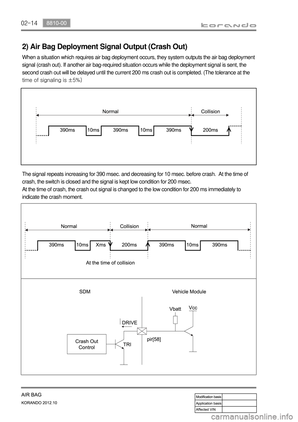
2) Air Bag Deployment Signal Output (Crash Out)
When a situation which requires air bag deployment occurs, they system outputs the air bag deployment
signal (crash out). If another air bag-required situation occurs while the deployment signal is sent, the
second crash out will be delayed until the current 200 ms crash out is completed. (The tolerance at the
time of signaling is ±5%)
The signal repeats increasing for 390 msec. and decreasing for 10 msec. before crash. At the time of
crash, the switch is closed and the signal is kept low condition for 200 msec.
At the time of crash, the crash out signal is changed to the low condition for 200 ms immediately to
indicate the crash moment.