2012 SKODA FABIA brake
[x] Cancel search: brakePage 142 of 196

Opening and closing the bonnet
Fig. 116
Bonnet/radiator grille release lever: Release lever Fig. 117
Securing the bonnet with the
bonnet support
First read and observe the introductory information and safety warn-
ings on page 138.
Opening
›
Pull the release lever under the dash panel 1
» Fig. 116.
Before opening the bonnet, ensure that the arms of the windscreen wipers are
correctly in place against the windscreen otherwise the paintwork could be dam-
aged.
› Press the release lever in the direction of the arrow 2
» Fig. 116 and the bon-
net is unlocked.
› Grab hold of the bonnet and lift.
› Take the bonnet support out of its holder and secure the opened bonnet by in-
serting the end of the support in the opening 3
» Fig. 117
designed for it.
ä Closing
› Lift the bonnet slightly and unhook the bonnet support. Press the bonnet sup-
port into the holder designed to hold it.
› Let the bonnet drop into the lock carrier lock from a height of around 20 cm –
do not push it in .
› Check that the bonnet is closed properly. Ð Engine compartment overview
Fig. 118
1.6 l/77 kW diesel engine
First read and observe the introductory information and safety warn-
ings on page 138.
Coolant expansion reservoir 143
Windscreen washer fluid reservoir 145
Engine oil filler opening 141
Engine oil dipstick 141
Brake fluid reservoir 144
Battery (below a cover) 145
Note
The location of the inspection points in the engine compartment of petrol and
diesel engines is practically identical. Ð
ä 1
2
3
4
5
6
140
General Maintenance
Page 146 of 196

Radiator fan
First read and observe the introductory information and safety warn-
ings on page 138.
The radiator fan is driven by an electric motor and controlled according to the
coolant temperature.
After switching off the ignition, the radiator fan can intermittently continue to op-
erate for approx. 10 minutes.
ÐChecking the brake fluid
Fig. 121
Engine compartment: Brake fluid
reservoir
First read and observe the introductory information and safety warn-
ings on page 138.
The brake fluid reservoir is located in the engine compartment.
›
Switch off the engine.
› Open the bonnet
» page 140.
› Check the level of brake fluid in the reservoir
» Fig. 121. The level must be be-
tween the “MIN” and “MAX” markings.
When driving, a slight drop in the fluid level is caused by the wear-and-tear and
automatic adjustment of the brake pads, and is therefore perfectly normal.
There may be an indication of a leak in the brake system, however, if the fluid lev-
el drops significantly within a short time or if it drops below the “MIN” marking. If
the brake fluid level is too low, this is indicated by the warning light lighting up
in the instrument cluster » page 18, Brake system .
ä
ä WARNING
If the fluid level has dropped below the MIN marking, do not continue your
journey - risk of accident! Seek help from a
ŠKODA specialist garage.Ð Changing the brake fluid
First read and observe the introductory information and safety warn-
ings on page 138.
Brake fluid absorbs moisture. Over time it therefore absorbs moisture from the
environment. Excessive water in the brake fluid may be the cause of corrosion in
the brake system. The water content also lowers the boiling point of the brake
fluid.
The brake fluid must comply with the following standards or specifications:
› VW 50114;
› FMVSS 116 DOT4. WARNING
Using old brake fluid can result in severe stress on the brakes because of the
formation of vapour bubbles in the brake system. This greatly impairs the
braking efficiency and thus also the safety of your vehicle. CAUTION
Brake fluid damages the paintwork of the vehicle. Ð
ä
144 General Maintenance
Page 156 of 196

Full wheel trim
First read and observe the introductory information and safety warn-
ings on page 150.
Pulling off
›
Hook the clamp found in the vehicle tool kit into the reinforced edge of the
wheel trim.
› Push the wheel wrench through the clamp, support on the tyre and pull off the
wheel trim.
Install
› First press the full wheel trim onto the wheel rim at the valve opening provided.
Then press the full wheel trim into the wheel rim until its entire circumference
locks correctly in place. CAUTION
■ Use the pressure of your hand, do not knock the full wheel trim! Heavy knocks
mainly on the points where the full wheel trim has not been inserted into the
wheel, can result in damage to the guide and centring elements of the full wheel
trim.
■ First of all check that the theft-deterrent wheel bolt is located in the hole near
the valve before fitting the full wheel trim onto a steel wheel which is attached
with a theft-deterrent wheel bolt » page 162, Securing wheels against theft .
■ If wheel trims are retrofitted it must be ensured that an adequate flow of air is
assured to cool the brake system. ÐWheel bolts
Fig. 128
Remove the cap
ä
First read and observe the introductory information and safety warn-
ings on page 150.
Pulling off
›
Push the plastic clip sufficiently far onto the cap until the inner catches of the
clip are positioned at the collar of the cap and detach the cap » Fig. 128.
Install
› Push the caps onto the wheel bolts up to the stop.
The wheel bolt caps are housed in a plastic box in the spare wheel or in the stor-
age space for the spare wheel. Ð Wheel trim caps
Fig. 129
Pull off the wheel trim cap on
light alloy wheels
First read and observe the introductory information and safety warn-
ings on page 150.
Pulling off
›
Carefully remove the wheel trim cap using the wire clamp from the vehicle tool
kit » Fig. 129. Ð
ä
ä
154 General Maintenance
Page 157 of 196

Tyre control display
Fig. 130
Button for setting the tyre infla-
tion pressure control value
First read and observe the introductory information and safety warn-
ings on page 150.
The tyre control display compares the speed and thus the rolling circumference of
the individual wheels with the help of the ABS sensors. If the rolling circumfer-
ence of a wheel is changed, the warning light
in the instrument clus-
ter » page 23, Tyre control display and an audible signal sounds.
The rolling circumference of the tyre can change if: › the tyre inflation pressure is too low;
› the structure of the tyre is damaged;
› the vehicle is loaded on one side;
› the wheels of an axle are loaded heavily (e.g. when towing a trailer or when
driving uphill or downhill);
› snow chains are mounted;
› the temporary spare wheel is mounted;
› one wheel per axle was changed.
Basic setting of the system
After changing the tyre inflation pressure, after changing one or several wheels,
the position of a wheel on the vehicle (e.g. exchanging the wheels between the
axles) or when the warning light lights up while driving, a basic setting of the sys-
tem must be carried out as follows:
› Inflate all of the tyres to the specified inflation pressure
» page 151, Service life
of tyres .
› Switch on the ignition.
ä
›
Press and hold the button
» Fig. 130 for longer than 2
seconds. While
pressing the button, the warning light illuminates. At the same time the sys-
tem memory is erased and the new calibration is started, which is confirmed
with an audible signal and then the warning light goes out.
› If the warning light
does not go out after the basic setting, this indicates a
system fault. Seek help from a ŠKODA specialist garage.
The warning light is lit
If the tyre inflation pressure of at least one wheel is insufficiently inflated in com-
parison to the stored basic value, the warning light » lights up.
The warning light flashes
If the warning light flashes, there is a system fault. Seek help from a
ŠKODA spe-
cialist garage to correct the fault. WARNING
■ When the warning light illuminates, immediately reduce the speed and
avoid sudden steering and brake manoeuvres. Stop the vehicle as soon as
possible and inspect the tyres and their inflation pressure.
■ Under certain circumstances (e.g. sporty style of driving, wintry or unpaved
roads) the warning light can be delayed or does not light up at all.
■ The tyre control display does not absolve the driver of the responsibility to
ensure the correct tyre inflation pressure. For this reason, the tyre inflation
pressure must be checked regularly. Note
■ The tyre control display does therefore not replace the regular tyre inflation
pressure control, as the system cannot detect an even loss of pressure. ■ The tyre control display cannot provide a warning in the event of very rapid tyre
inflation pressure loss, e.g. in the case of sudden tyre damage. In this case care-
fully bring the vehicle to a standstill without sudden steering movements or
sharp braking.
■ To ensure a proper functioning of the tyre control display, it is necessary to re-
peat the basic setting every 10 000 km or once a year. Ð
155
Wheels and Tyres
Page 158 of 196

Wheel bolts
First read and observe the introductory information and safety warn-
ings on page 150.
Wheels and
wheel bolts are matched to each other in terms of design. Each time
you fit other wheels, e.g. light alloy wheels or wheels with winter tyres, you must
therefore also use the matching wheel bolts of the correct length and shape of
spherical cap. This is essential to ensure that the wheels are tightly fitted and
that the brake system operates properly. ÐWinter tyres
First read and observe the introductory information and safety warn-
ings on page 150.
The handling of your vehicle will be significantly improved when driving on wintry
roads if you fit winter tyres. Summer tyres do not offer the same grip on ice, snow
and at temperatures below 7 °C because of their construction (width, rubber
blend, tread pattern). This particularly applies to vehicles which are equipped with
low-profile tyres
or high-speed tyres (code index H or V on wall of tyre).
To achieve the best possible handling properties, winter tyres must be fitted on
all 4 wheels, the minimum tread depth must be 4
mm and tyres must be no older
than 4 years.
Winter tyres of a lower speed category can be used provided that the permissible
maximum speed of these tyres is not exceeded even if the possible maximum
speed of the vehicle is higher. For the sake of the environment
Fit the summer tyres on again in good time as they provide better handling prop-
erties, a shorter braking distance, less tyre noise, and reduced tyre wear on roads
which are free of snow and ice as well as at temperatures above 7
°C. The fuel
consumption is also lower. ÐSnow chains
First read and observe the introductory information and safety warn-
ings on page 150.ä
ä
ä Snow chains must only be mounted on the front wheels.
When driving on wintry roads, snow chains improve not only traction, but also the
braking performance.
For technical reasons, it is only permissible to fit snow chains with the following
wheel/tyre combinations.
Wheel size Depth (D)Tyre size
5J x 14 35 mm 165/70
6J x 14 37 mm185/60
6J x 15 43 mm 185/55 Only fit snow chains with links and locks not larger than
12
mm.
Remove the full wheel trims before installing the snow chains.
Observe the national legal regulations relating to the use of snow chains and the
maximum vehicle speed with snow chains. CAUTION
The chains must be removed when driving on roads which are free of snow. They
adversely affect the handling of your vehicle, damage the tyres and are rapidly
destroyed. Ð156
General Maintenance
Page 162 of 196

›
In the event of a puncture, park the vehicle as far away as possible from the
flow of traffic. The place you choose should be level.
› Let all of the occupants get out.
While changing a tyre, the occupants of the
vehicle should not stand on the road (instead they should remain behind a crash
barrier).
› Switch off the engine and move the gearshift lever into
Neutral or move the
selector lever for the automatic gearbox into position P .
› Firmly apply the
handbrake.
› If a trailer is connected, remove it.
› Remove the vehicle tool kit
» page 158 and the spare wheel » page 153, Spare
wheel from the boot. ÐChanging a wheel
First read and observe the introductory information and safety warn-
ings on page 159.
Always change a wheel on a level surface as far as possible.
›
Remove the full wheel trim
» page 154
or caps » page 154.
› In the case of light alloy wheel rims remove the wheel trim cap
» page 154.
› First of all slacken the anti-theft wheel bolt and then the other wheel
bolts » page 161.
› Jack up the vehicle until the wheel that needs changing is clear of the
ground » page 161.
› Unscrew the wheel bolts and place them on a clean surface (cloth, paper, etc.).
› Remove the wheel.
› Attach the spare wheel and slightly screw on the wheel bolts.
› Lower the vehicle.
› Alternately tighten the wheel bolts opposite each other using the wheel
wrench (crosswise) and then tighten the anti-theft wheel bolt » page 161.
› Reinstall the wheel trim/wheel trim cap or the caps. Note
■ All bolts must be clean and must turn easily.
■ Under no circumstances grease or oil the wheel bolts!
■ When fitting unidirectional tyres, ensure that the direction of rotation is cor-
rect »
page 153, Unidirectional tyres . Ð
ä Subsequent steps
First read and observe the introductory information and safety warn-
ings on page 159.
The following steps must also be performed after changing the wheel.
›
Stow and attach the replaced wheel in the spare wheel well using a special
screw » page 153, Spare wheel.
› Stow the vehicle tool kit in the space provided.
› Check
the tyre pressure
on the installed spare wheel as soon as possible.
› Have the
tightening torque of the wheel bolts checked with a torque wrench
as soon as possible.
› Change the damaged wheel or consult a ŠKODA specialist garage about repair
possibilities. Note
■ If it is determined that the wheel bolts are corroded and difficult to turn when
changing the wheel, the bolts must be replaced before checking the tightening
torque. ■ Drive cautiously and only at a moderate speed until the tightening torque has
been checked. Ð
ä
160 Do-it-yourself
Page 165 of 196

WARNING (Continued)
■ Do not drive faster than 80 km/h (50 mph).
■ Avoid accelerating at full throttle, sharp braking and fast cornering.
■ Check the tyre inflation pressure after driving for 10 minutes!
■ The sealant is hazardous to heath. Remove immediately if it comes into con-
tact with the skin. For the sake of the environment
Used sealant or sealant whose expiry date has passed must be disposed of in ac-
cordance with environmental protection regulations. Note
■ Observe the manufacturer's usage instructions for the breakdown kit.
■ A new bottle of sealant can be purchased from ŠKODA Original Accessories.
■ Immediately replace the wheel that was repaired using the breakdown kit or
consult a ŠKODA specialist garage about repair possibilities. ÐComponents of the breakdown kit
Fig. 137
Components of the breakdown kit
First read and observe the introductory information and safety warn-
ings on page 162.
ä The breakdown kit contains the following parts:
Valve remover
Sticker with speed designation
“max. 80 km/h”/“max. 50 mph”
Inflation hose with plug
Air compressor
Tyre inflation hose
Tyre inflation hose
Air release valve
ON and OFF switch
12 volt cable connector
Tyre inflator bottle with sealing agent
Replacement valve core
The valve remover 1
has a slot at its lower end which fits into the valve core.
This is the only way in which you can remove and re-install the valve core from
the tyre valve. The same also applies to the replacement valve core 11
.
Ð Preparing to use the breakdown kit
First read and observe the introductory information and safety warn-
ings on page 162.
The following preparatory work must be carried out before using the breakdown
kit.
›
In the event of a puncture, park the vehicle as far away as possible from the
flow of traffic. Park on as flat and firm a surface as possible.
› Let all of the occupants get out.
While changing a tyre, the occupants of the
vehicle should not stand on the road (instead they should remain behind a crash
barrier).
› Switch off the engine and move the gearshift lever into
Neutral or move the
selector lever
for the automatic gearbox into position P .
› Firmly apply the
handbrake.
› Check that you can carry out the repairs with the breakdown kit
» page 162.
› If a trailer is connected, remove it.
› Remove the breakdown kit
from the boot.
› Stick the sticker 2
»
Fig. 137 on page 163 on the dash panel in view of the driv-
er.
› Do not remove the foreign body, e.g. screw or nail, from the tyre.
› Unscrew the valve cap.
£ 1
2
3
4
5
6
7
8
9
10
11
ä
163
Do-it-yourself
Page 168 of 196
›
Attach the other end 4
to a solid metal part which is connected firmly to the
engine block, or to the engine block itself.
Starting engine
› Start the engine on the vehicle providing the power and allow it to idle.
› Now start the engine of the vehicle with the discharged battery.
› If the engine does not start, terminate the attempt to start the engine after
10 seconds and wait for about 30 seconds before repeating the process.
› Disconnect the cables in exactly the
reverse order to the one described above. ÐJump-starting in vehicles with the START-STOP system
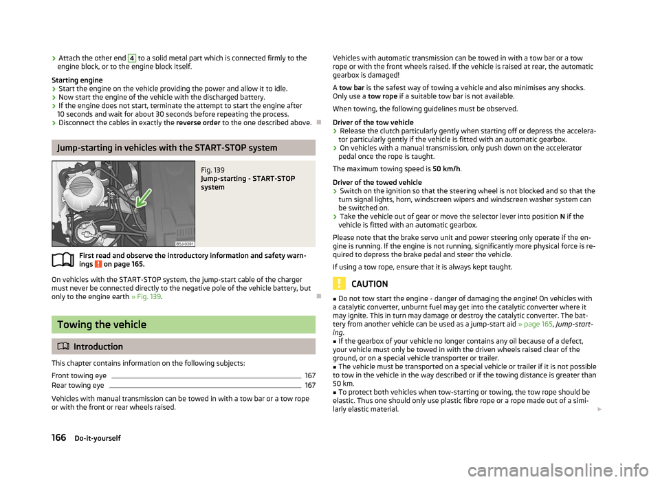
Fig. 139
Jump-starting - START-STOP
system
First read and observe the introductory information and safety warn-
ings on page 165.
On vehicles with the START-STOP system, the jump-start cable of the charger
must never be connected directly to the negative pole of the vehicle battery, but
only to the engine earth » Fig. 139. ÐTowing the vehicle
ä
Introduction
This chapter contains information on the following subjects:
Front towing eye 167
Rear towing eye 167
Vehicles with manual transmission can be towed in with a tow bar or a tow rope
or with the front or rear wheels raised.
ä Vehicles with automatic transmission can be towed in with a tow bar or a tow
rope or with the front wheels raised. If the vehicle is raised at rear, the automatic
gearbox is damaged!
A tow bar
is the safest way of towing a vehicle and also minimises any shocks.
Only use a tow rope if a suitable tow bar is not available.
When towing, the following guidelines must be observed.
Driver of the tow vehicle
› Release the clutch particularly gently when starting off or depress the accelera-
tor particularly gently if the vehicle is fitted with an automatic gearbox.
› On vehicles with a manual transmission, only push down on the accelerator
pedal once the rope is taught.
The maximum towing speed is 50 km/h.
Driver of the towed vehicle
› Switch on the ignition so that the steering wheel is not blocked and so that the
turn signal lights, horn, windscreen wipers and windscreen washer system can
be switched on.
› Take the vehicle out of gear or move the selector lever into position
N if the
vehicle is fitted with an automatic gearbox.
Please note that the brake servo unit and power steering only operate if the en-
gine is running. If the engine is not running, significantly more physical force is re-
quired to depress the brake pedal and steer the vehicle.
If using a tow rope, ensure that it is always kept taught. CAUTION
■ Do not tow start the engine - danger of damaging the engine! On vehicles with
a catalytic converter, unburnt fuel may get into the catalytic converter where it
may ignite. This in turn may damage or destroy the catalytic converter. The bat-
tery from another vehicle can be used as a jump-start aid » page 165, Jump-start-
ing .
■ If the gearbox of your vehicle no longer contains any oil because of a defect,
your vehicle must only be towed in with the driven wheels raised clear of the
ground, or on a special vehicle transporter or trailer.
■ The vehicle must be transported on a special vehicle or trailer if it is not possible
to tow in the vehicle in the way described or if the towing distance is greater than
50 km. ■ To protect both vehicles when tow-starting or towing, the tow rope should be
elastic. Thus one should only use plastic fibre rope or a rope made out of a simi-
larly elastic material. £
166 Do-it-yourself