Page 135 of 184
133
6
ACCESSORIE
S
Towing a trailer
TOWING A TRAILER, CARAVAN, BOAT, ETC...
For more information about weights,
refer to the administrative documents (V5
registration document, ...)
Distribution of loads:
distribute the load in
the trailer so that the heaviest objects are as
close as possible to the axle and the nose
weight is close to the maximum authorised
without, however, exceeding it.
Driving advice
A towed vehicle must free wheel: gearbox in
neutral.
Page 137 of 184
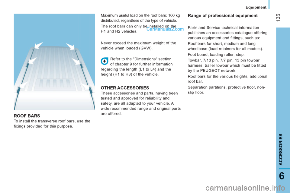
ROOF BARS
To install the transverse roof bars, use the
fixings provided for this purpose. Refer to the "Dimensions" section
of chapter 9 for further information
regarding the length (L1 to L4) and the
height (H1 to H3) of the vehicle. Never exceed the maximum weight of the
vehicle when loaded (GVW).
OTHER ACCESSORIES
These accessories and parts, having been
tested and approved for reliability and
safety, are all adapted to your vehicle. A
wide recommended range and original parts
are offered.
Range of professional equipment Maximum useful load on the roof bars: 100 kg
distributed, regardless of the type of vehicle.
The roof bars can only be installed on the
H1 and H2 vehicles. Parts and Service technical information
publishes an accessories catalogue offering
various equipment and fittings, such as:
Roof bars for short, medium and long
wheelbase (load retainers for all models).
Foot board, loading roller, step.
Towbar, 7/13 pin, 7/7 pin, 13 pin towbar
harness: trailer towbar which must be fitted
by the PEUGEOT network.
Roof bars for the various heights, additional
roof bar.
Separation partitions, protective floor, non-
slip floor.
Equipment
135
6
ACCESSORIE
S
Page 150 of 184
Changing a wheel
14
8
1. PARKING THE VEHICLE
As far as possible, park the vehicle on level,
stable and non-slippery ground.
Apply the parking brake, switch off the
ignition and engage first gear.
Put on a high visibility vest and position the
warning triangle.
If possible, place a chock under the
wheel diagonally opposite the wheel to be
changed. 2. TOOLS
These are located under the front passenger
seat cushion.
- Turn the button a quarter of a turn then
pull the box.
- After use, press the button then turn it a
quarter of a turn to secure the box.
A.
Long socket.
B.
Ratchet wrench.
C.
Jack.
D.
Towing hook.
E.
Wheelbrace.
F.
Screwdriver.
CHANGING A WHEEL
You must ensure that the occupants get out
of the vehicle and wait in a safe location.
Page 151 of 184
Changing a wheel
14
9
QUICK HELP
8
4. OPERATING PROCEDURE
- Remove the trim using the screwdriver F
as a lever.
- Release the bolts using the
wheelbrace E
.
- Position the jack C
at one of the four
locations provided on the underbody
near the wheels.
3. SPARE WHEEL
The spare wheel retaining bolt is located
below the bumper on the right.
- Turn the bolt using the socket A
and the
ratchet wrench B
to release the wheel.
- Turn to the locking point, indicated by
an increase in the force required for the
manoeuvre.
- Take out the spare wheel using the
wrench.
- Unscrew the handle G
and remove the
support H
.
- Release the spare wheel and place it
near the wheel to be changed.
If you have a retractable foot board, the jack
must be positioned at 45°.
- Extend the jack using the ratchet
wrench B
until the wheel is a few
centimetres off the ground.
- Unscrew the bolts fully and change the
wheel.
Page 152 of 184
Changing a wheel
150
6. REFITTING THE REPAIRED WHEEL
Refitting of the wheel is identical to step 5,
do not forget to refit the wheel trim.
Refer to the "Identification markings"
section of chapter 9 to locate the tyre
label.
The spare wheel is not designed to be used
over long distances. Have the tightening of
the bolts and pressure of the spare wheel
checked by a PEUGEOT dealer without
delay.
Also, have the original wheel repaired and
refitted by a PEUGEOT dealer as soon as
possible.
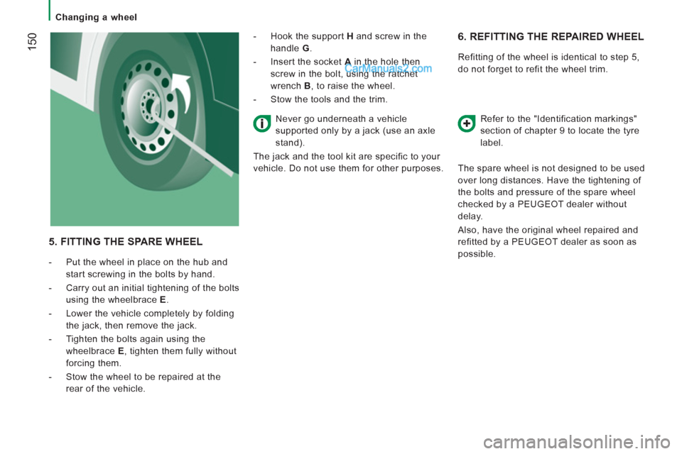
5. FITTING THE SPARE WHEEL
- Put the wheel in place on the hub and
start screwing in the bolts by hand.
- Carry out an initial tightening of the bolts
using the wheelbrace E
.
- Lower the vehicle completely by folding
the jack, then remove the jack.
- Tighten the bolts again using the
wheelbrace E
, tighten them fully without
forcing them.
- Stow the wheel to be repaired at the
rear of the vehicle.
- Hook the support H
and screw in the
handle G
.
- Insert the socket A
in the hole then
screw in the bolt, using the ratchet
wrench B
, to raise the wheel.
- Stow the tools and the trim.
Never go underneath a vehicle
supported only by a jack (use an axle
stand).
The jack and the tool kit are specific to your
vehicle. Do not use them for other purposes.
Page 153 of 184
Changing a wheel
151
QUICK HELP
8
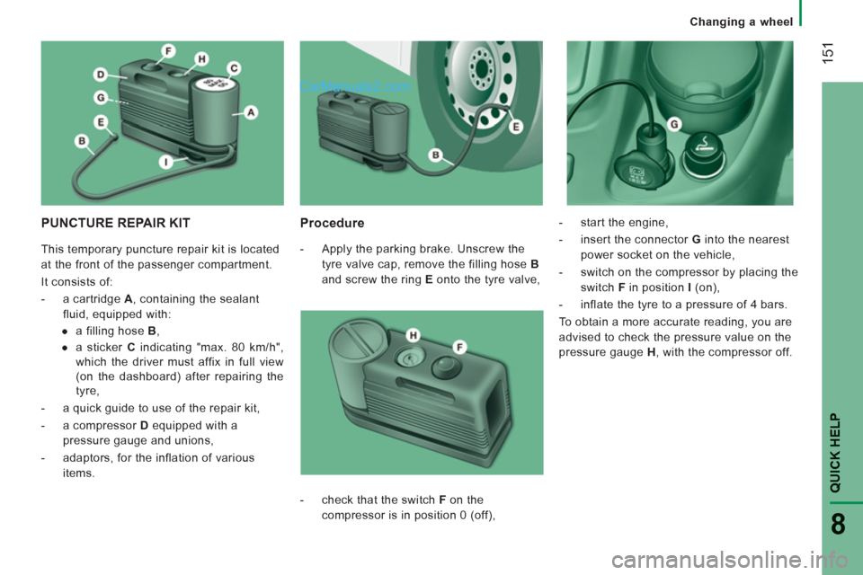
PUNCTURE REPAIR KIT
Procedure
- Apply the parking brake. Unscrew the
tyre valve cap, remove the filling hose B
and screw the ring E
onto the tyre valve,
- start the engine,
- insert the connector G
into the nearest
power socket on the vehicle,
- switch on the compressor by placing the
switch F
in position I
(on),
- inflate the tyre to a pressure of 4 bars.
To obtain a more accurate reading, you are
advised to check the pressure value on the
pressure gauge H
, with the compressor off.
- check that the switch F
on the
compressor is in position 0 (off), This temporary puncture repair kit is located
at the front of the passenger compartment.
It consists of:
- a cartridge A
, containing the sealant
fluid, equipped with:
●
a filling hose B
,
●
a sticker C
indicating "max. 80 km/h",
which the driver must affix in full view
(on the dashboard) after repairing the
tyre,
- a quick guide to use of the repair kit,
- a compressor D
equipped with a
pressure gauge and unions,
- adaptors, for the inflation of various
items.
Page 154 of 184
Changing a wheel
152
- If a pressure of at least 3 bars
is not
reached within 5 minutes, disconnect
the compressor from the valve and the
power socket, then move the vehicle
forward by approximately 10 metres to
distribute the sealant fluid inside the
tyre.
- Then repeat the inflating operation:
●
if a pressure of at least 3 bars
is not
reached within 10 minutes, switch off
your vehicle: the tyre has suffered
too much damage and repair has not
been possible. Consult a PEUGEOT
dealer.
●
if the tyre has been inflated to a
pressure of 4 bars
, set off again
immediately.
After driving for approximately 10 minutes,
stop and check the pressure of the tyre
again.
Adjust the pressure if necessary and contact
a PEUGEOT dealer as soon as possible.
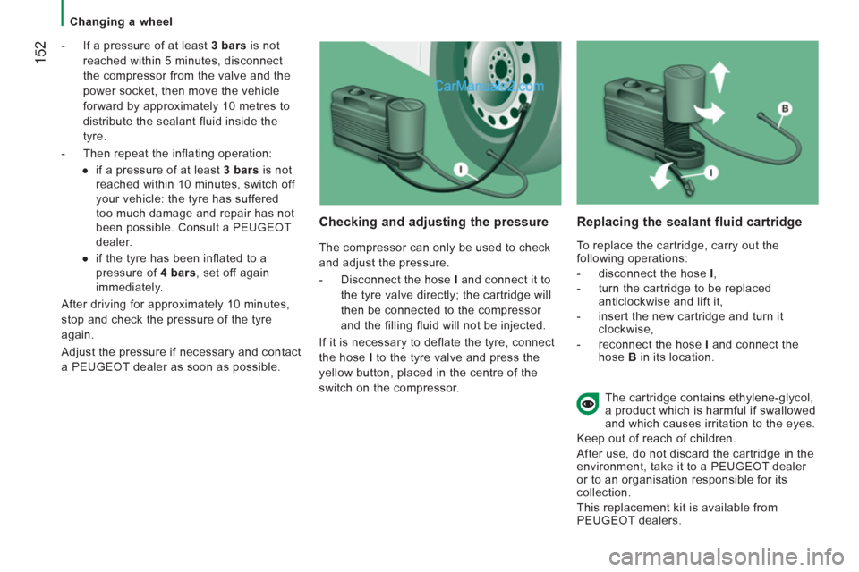
Checking and adjusting the pressure
The compressor can only be used to check
and adjust the pressure.
- Disconnect the hose I
and connect it to
the tyre valve directly; the cartridge will
then be connected to the compressor
and the filling fluid will not be injected.
If it is necessary to deflate the tyre, connect
the hose I
to the tyre valve and press the
yellow button, placed in the centre of the
switch on the compressor.
Replacing the sealant fluid cartridge
To replace the cartridge, carry out the
following operations:
- disconnect the hose I
,
- turn the cartridge to be replaced
anticlockwise and lift it,
- insert the new cartridge and turn it
clockwise,
- reconnect the hose I
and connect the
hose B
in its location.
The cartridge contains ethylene-glycol,
a product which is harmful if swallowed
and which causes irritation to the eyes.
Keep out of reach of children.
After use, do not discard the cartridge in the
environment, take it to a PEUGEOT dealer
or to an organisation responsible for its
collection.
This replacement kit is available from
PEUGEOT dealers.
Page 156 of 184
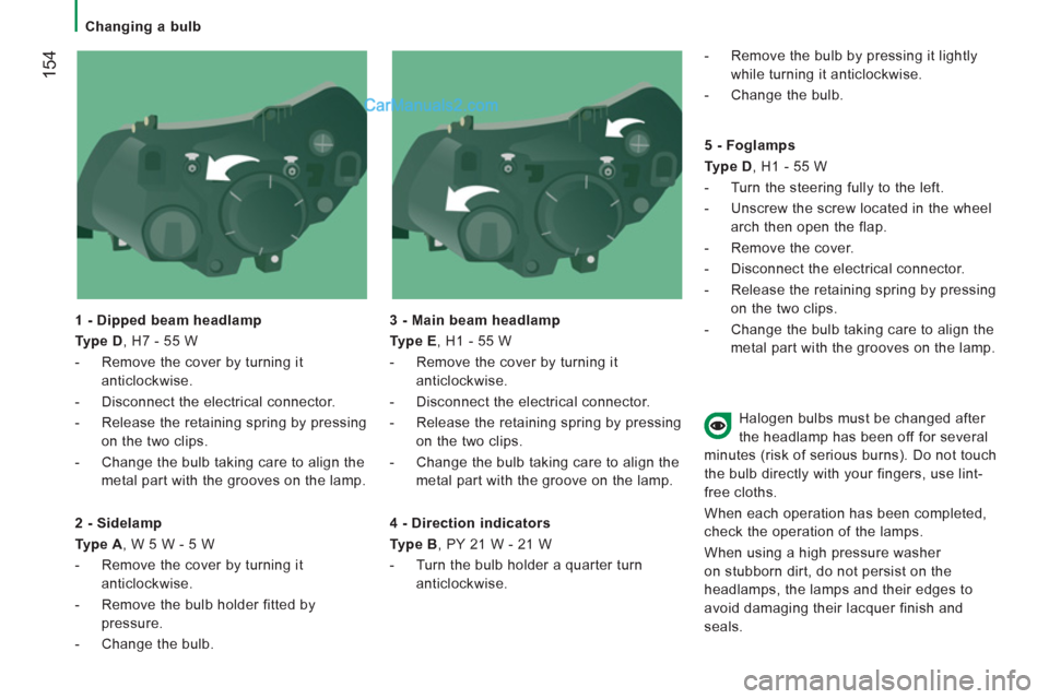
Changing a bulb
154
1 - Dipped beam headlamp
Type D
, H7 - 55 W
- Remove the cover by turning it
anticlockwise.
- Disconnect the electrical connector.
- Release the retaining spring by pressing
on the two clips.
- Change the bulb taking care to align the
metal part with the grooves on the lamp.
3 - Main beam headlamp
Type E
, H1 - 55 W
- Remove the cover by turning it
anticlockwise.
- Disconnect the electrical connector.
- Release the retaining spring by pressing
on the two clips.
- Change the bulb taking care to align the
metal part with the groove on the lamp.
2 - Sidelamp
Type A
, W 5 W - 5 W
- Remove the cover by turning it
anticlockwise.
- Remove the bulb holder fitted by
pressure.
- Change the bulb.
4 - Direction indicators
Type B
, PY 21 W - 21 W
- Turn the bulb holder a quarter turn
anticlockwise.
- Remove the bulb by pressing it lightly
while turning it anticlockwise.
- Change the bulb.
5 - Foglamps
Type D
, H1 - 55 W
- Turn the steering fully to the left.
- Unscrew the screw located in the wheel
arch then open the flap.
- Remove the cover.
- Disconnect the electrical connector.
- Release the retaining spring by pressing
on the two clips.
- Change the bulb taking care to align the
metal part with the grooves on the lamp.
Halogen bulbs must be changed after
the headlamp has been off for several
minutes (risk of serious burns). Do not touch
the bulb directly with your fingers, use lint-
free cloths.
When each operation has been completed,
check the operation of the lamps.
When using a high pressure washer
on stubborn dirt, do not persist on the
headlamps, the lamps and their edges to
avoid damaging their lacquer finish and
seals.