Page 13 of 341
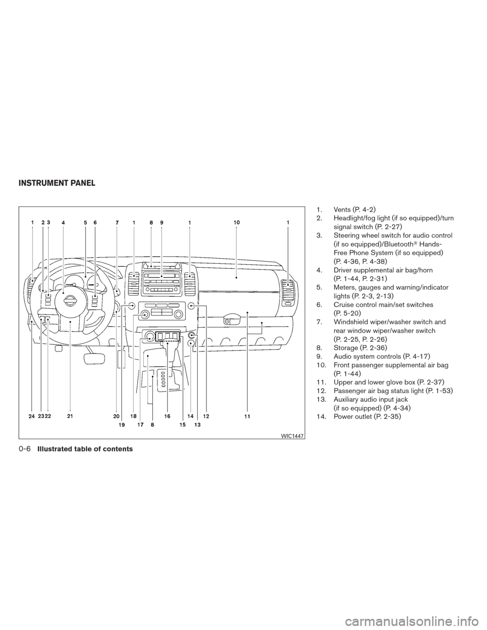
1. Vents (P. 4-2)
2. Headlight/fog light (if so equipped)/turnsignal switch (P. 2-27)
3. Steering wheel switch for audio control
(if so equipped)/Bluetooth �Hands-
Free Phone System (if so equipped)
(P. 4-36, P. 4-38)
4. Driver supplemental air bag/horn
(P. 1-44, P. 2-31)
5. Meters, gauges and warning/indicator
lights (P. 2-3, 2-13)
6. Cruise control main/set switches
(P. 5-20)
7. Windshield wiper/washer switch and
rear window wiper/washer switch
(P. 2-25, P. 2-26)
8. Storage (P. 2-36)
9. Audio system controls (P. 4-17)
10. Front passenger supplemental air bag
(P. 1-44)
11. Upper and lower glove box (P. 2-37)
12. Passenger air bag status light (P. 1-53)
13. Auxiliary audio input jack
(if so equipped) (P. 4-34)
14. Power outlet (P. 2-35)
WIC1447
INSTRUMENT PANEL
0-6Illustrated table of contents
Page 14 of 341
15. Electronic locking rear differential(E-Lock) system switch
(if so equipped) (P. 2-33)
Hill descent control switch
(if so equipped) (P. 2-32)
Vehicle Dynamic Control (VDC) OFF
switch (P. 2-32)
16. Shift selector (P. 5-13)
17. 4WD shift switch (P. 5-27)
18. Climate controls (P.4-3, 4-10)
19. Hazard warning flasher switch (P. 2-31)
20. Ignition switch (P. 5-10)
21. Tilt steering wheel control (P. 3-12)
22. Off road lamps switch (if so equipped)
(P. 2-30)
23. Clutch interlock (clutch start) switch
(if so equipped) (P. 2-34)
24. Power outside mirror controls
(if so equipped) (P. 3-15)
See the page number indicated in paren-
theses for operating details.
Illustrated table of contents0-7
Page 15 of 341
VQ40DE engine
1. Windshield-washer fluid reservoir(P. 8-13)
2. Fuse/fusible link box (P. 8-22)
3. Fuse and relay box (P. 8-22)
4. Engine oil filler cap (P. 8-9)
5. Engine oil dipstick (P. 8-9)
6. Brake fluid reservoir/Clutch fluid
reservoir (M/T model) (P. 8-12)
7. Air cleaner (P. 8-18)
8. Drive belt location (P.8-16)
9. Radiator cap (P. 8-7)
10. Power steering fluid reservoir (P. 8-12)
11. Battery (P. 8-14)
12. Engine coolant reservoir (P. 8-7)
See the page number indicated in paren-
theses for operating details.
LII0167
ENGINE COMPARTMENT CHECK
LOCATIONS
0-8Illustrated table of contents
Page 81 of 341
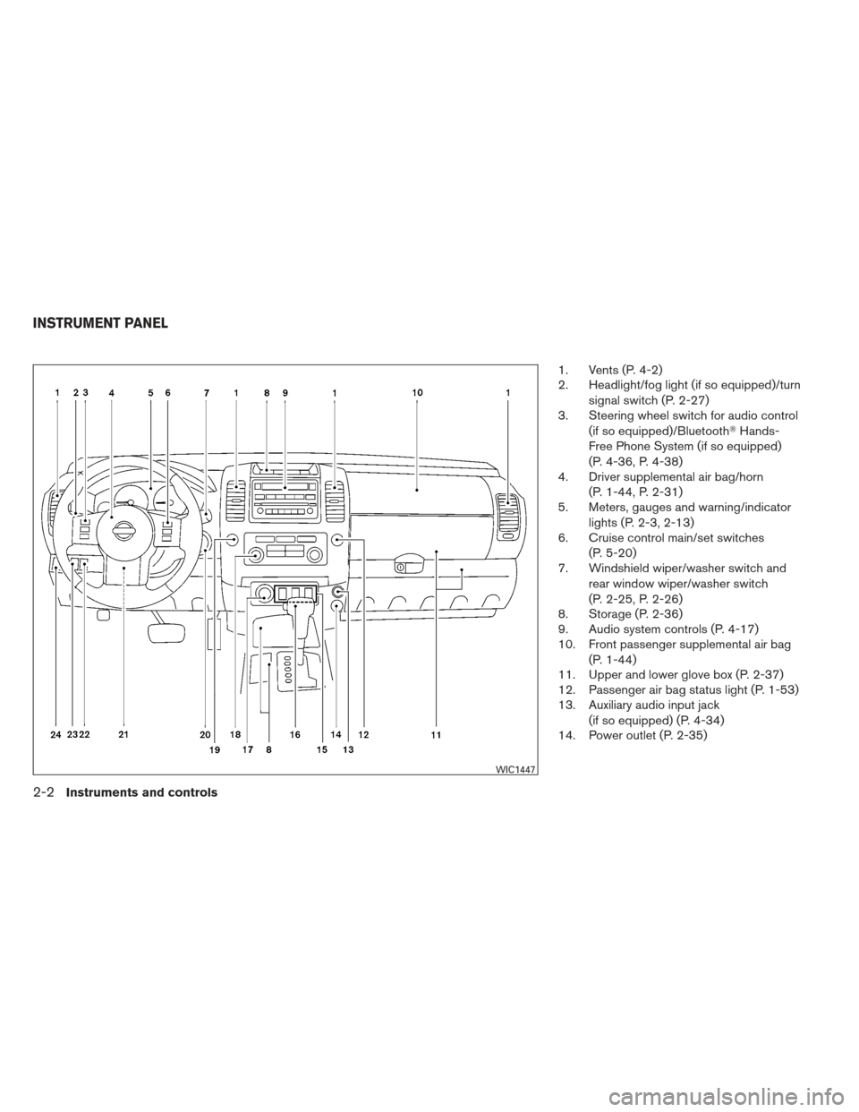
1. Vents (P. 4-2)
2. Headlight/fog light (if so equipped)/turnsignal switch (P. 2-27)
3. Steering wheel switch for audio control
(if so equipped)/Bluetooth �Hands-
Free Phone System (if so equipped)
(P. 4-36, P. 4-38)
4. Driver supplemental air bag/horn
(P. 1-44, P. 2-31)
5. Meters, gauges and warning/indicator
lights (P. 2-3, 2-13)
6. Cruise control main/set switches
(P. 5-20)
7. Windshield wiper/washer switch and
rear window wiper/washer switch
(P. 2-25, P. 2-26)
8. Storage (P. 2-36)
9. Audio system controls (P. 4-17)
10. Front passenger supplemental air bag
(P. 1-44)
11. Upper and lower glove box (P. 2-37)
12. Passenger air bag status light (P. 1-53)
13. Auxiliary audio input jack
(if so equipped) (P. 4-34)
14. Power outlet (P. 2-35)
WIC1447
INSTRUMENT PANEL
2-2Instruments and controls
Page 82 of 341
15. Electronic locking rear differential(E-Lock) system switch
(if so equipped) (P. 2-33)
Hill descent control switch
(if so equipped) (P. 2-32)
Vehicle Dynamic Control (VDC) OFF
switch (P. 2-32)
16. Shift selector (P. 5-13)
17. 4WD shift switch (P. 5-27)
18. Climate controls (P.4-3, 4-10)
19. Hazard warning flasher switch (P. 2-31)
20. Ignition switch (P. 5-10)
21. Tilt steering wheel control (P. 3-12)
22. Off road lamps switch (if so equipped)
(P. 2-30)
23. Clutch interlock (clutch start) switch
(if so equipped) (P. 2-34)
24. Power outside mirror controls
(if so equipped) (P. 3-15)
See the page number indicated in paren-
theses for operating details.
1. Warning/indicator lights
2. Tachometer
3. Speedometer
4. Fuel gauge
5. Voltmeter 6. Odometer/Twin trip odometer/Trip
computer (if so equipped)
7. Engine oil pressure gauge
8. Engine coolant temperature gauge
WIC0911
METERS AND GAUGES
Instruments and controls2-3
Page 111 of 341
 system on for most driv-
ing conditions.
If the vehicle is stuck in mud or snow, the VDC
system reduces the engine output to reduce")
The vehicle should be driven with the Vehicle
Dynamic Control (VDC) system on for most driv-
ing conditions.
If the vehicle is stuck in mud or snow, the VDC
system reduces the engine output to reduce
wheel spin. The engine speed will be reduced
even if the accelerator is depressed to the floor. If
maximum engine power is needed to free a stuck
vehicle, turn the VDC system off.
To turn off the VDC system, push the VDC OFF
switch. The
indicator will come on.
Push the VDC OFF switch again or restart the
engine to turn on the system. See “Vehicle Dy-
namic Control (VDC) system” in the “Starting and
driving” section.
WARNING
● Never rely solely on the hill descent
control system to control vehicle speed
when driving on steep downhill grades.
Always drive carefully when using the
hill descent control system and decel-
erate the vehicle speed by depressing
the brake pedal if necessary. Be espe-
cially careful when driving on frozen,
muddy or extremely steep downhill
roads. Failure to control vehicle speed
may result in a loss of control of the
vehicle and possible serious injury or
death. ●
The hill descent control may not control
the vehicle speed on a hill under all load
or road conditions. Always be prepared
to depress the brake pedal to control
vehicle speed. Failure to do so may re-
sult in a collision or serious personal
injury.
CAUTION
When the hill descent control system op-
erates continuously for a long time, the
temperature of the brake pads may in-
crease and the hill descent control system
may be temporarily disabled (the indicator
light will blink) . If the indicator light does
not come on continuously after blinking,
stop using the system.
The hill descent control system is designed to
reduce driver workload when going down steep
hills. The hill descent control system helps to
control vehicle speed so the driver can concen-
trate on steering the vehicle.
To activate the hill descent control system: ● the 4WD switch must be in the 4L position
and the vehicle speed must be under 15
MPH (25 km/h) or
LIC1548LIC0743
VEHICLE DYNAMIC CONTROL (VDC)
OFF SWITCH HILL DESCENT CONTROL SWITCH (if
so equipped)
2-32Instruments and controls
Page 130 of 341

3 Pre-driving checks and adjustments
Keys .............................................3-2NISSAN Vehicle Immobilizer System keys .........3-2
Doors ............................................3-3
Locking with key ................................3-3
Locking with inside lock knob ....................3-3
Locking with power door lock switch .............3-4
Automatic door locks ...........................3-4
Child safety rear door lock .......................3-5
Remote keyless entry system .......................3-5
How to use remote keyless entry system ..........3-6
Hood ............................................3-9
Lift gate ..........................................3-9 Fuel-filler door
................................... 3-10
Opening the fuel-filler lid .......................3-10
Fuel-filler cap . . ............................... 3-10
Steering wheel ................................... 3-12
Tilt operation .................................. 3-12
Sun visors ....................................... 3-12
Vanity mirrors (if so equipped) ...................3-13
Mirrors .......................................... 3-13
Rearview mirror (if so equipped) .................3-13
Automatic anti-glare rearview mirror
(if so equipped) ............................... 3-14
Outside mirrors ............................... 3-14
Page 181 of 341

The audio system can be operated using t")
1. Volume control switch
2. Phone operation switch
3. Power on and MODE select switch
4. Tuning switch
STEERING WHEEL SWITCH FOR
AUDIO CONTROL (if so equipped)
The audio system can be operated using the
controls on the steering wheel.
POWER on/off switch
If you have the Type A switch, with the ignition
switch placed in the ACC or ON position, push
the POWER switch to turn the audio system on
or off.
If you have the Type B switch, with the ignition
switch placed in the ACC or ON position, push
the MODE switch to turn the audio system on.
MODE select switch
Push the mode select switch to change the
modes:
PRESET A→PRESET B →PRESET C →CD*
→ AUX** →PRESET A
*This mode is only available when a CD is loaded.
**This mode is only available when a compatible
auxiliary device is plugged into the AUX jack.
Volume control switch
Push the volume control switch up or down to
increase or decrease the volume.
Tuning
Memory change (radio):
Push the tuning switch (
or) for less
than 1.5 seconds to change to the next or previ-
ous preset.
Seek tuning (radio):
Push the tuning switch (
or) for
more than 1.5 seconds to seek the next or previ-
ous radio station.
Next/Previous track (CD):
Push the tuning switch
orfor less
than 1.5 seconds to return to the beginning of the
present track or skip to the next track. Push
several times to skip back or skip through tracks.
Change disc (CD) (if so equipped):
Push the SEEK tuning switch
orfor
more than 1.5 seconds to change the playing
disc up or down.
Type B
LHA1087
4-36Heater, air conditioner, audio and phone systems
 system switch
(if so equipped) (P. 2-33)
Hill descent control switch
(if so equipped) (P. 2-32)
Vehicle Dynamic Control (VDC) OFF
switch (P. 2-32)
16.")

2. Fuse/fusible link box (P. 8-22)
3. Fuse and relay box (P. 8-22)
4. Engine oil filler cap (P. 8-9)
5. Engine oil dipstick (P. 8-9)
6. Brak")
 system switch
(if so equipped) (P. 2-33)
Hill descent control switch
(if so equipped) (P. 2-32)
Vehicle Dynamic Control (VDC) OFF
switch (P. 2-32)
16.")