2012 NISSAN QASHQAI fog light
[x] Cancel search: fog lightPage 79 of 297

Downloaded from www.Manualslib.com manuals search engine WARNING
Take care as the power outlet and plug may be
hot during or immediately after use.
CAUTION
This power outlet is not designed for use with
a cigarette lighter unit.
Do not use with accessories that exceed a 12
volt, 120 W (10 A) power draw. Do not use
double adaptors or more than one electrical
accessory.
Use this power outlet with the engine running
(do not use for extended periods of time with
the engine stopped or idling).
Avoid using when the air conditioner, head-
lights or rear window defogger are on.
When not in use, be sure that the cap is
closed. Do not allow water to come into con-
tact with the outlet.
Before inserting or disconnecting a plug, be
sure to turn off the power switch of the elec-
trical accessory being used or the Acc power
of the vehicle.
Fully push the plug in sufficiently. If sufficient
contact is not made, the plug may overheat or
the internal temperature fuse may blow.
NIC1372Z
Front row
NIC1451
2nd row (7-seater)
POWER OUTLET
2-30Instruments and controls
Page 121 of 297

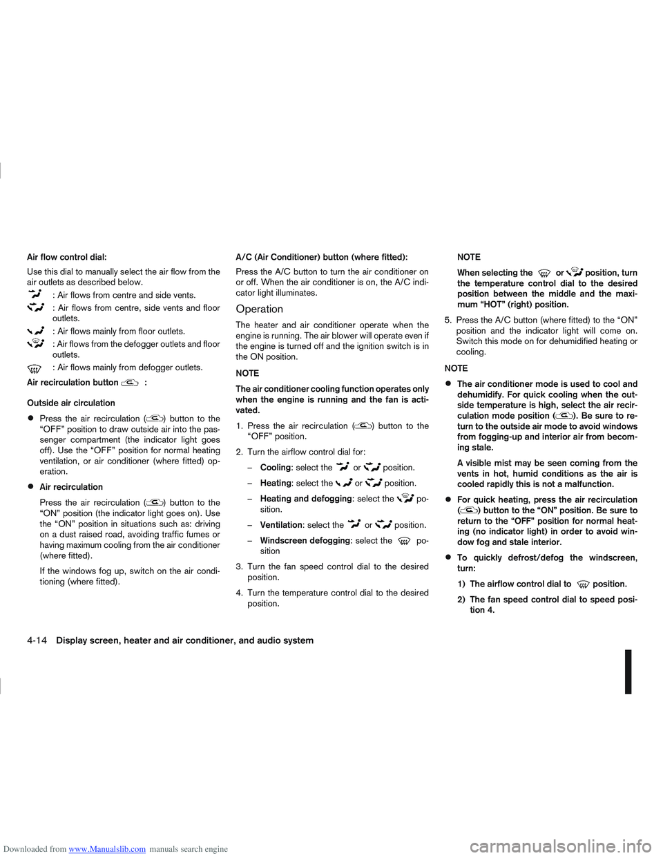
Downloaded from www.Manualslib.com manuals search engine Air flow control dial:
Use this dial to manually select the air flow from the
air outlets as described below.
: Air flows from centre and side vents.
: Air flows from centre, side vents and floor
outlets.
: Air flows mainly from floor outlets.
: Air flows from the defogger outlets and floor
outlets.
: Air flows mainly from defogger outlets.
Air recirculation button
m:
Outside air circulation
Press the air recirculation () button to the
“OFF” position to draw outside air into the pas-
senger compartment (the indicator light goes
off). Use the “OFF” position for normal heating
ventilation, or air conditioner (where fitted) op-
eration.
Air recirculation
Press the air recirculation (
) button to the
“ON” position (the indicator light goes on). Use
the “ON” position in situations such as: driving
on a dust raised road, avoiding traffic fumes or
having maximum cooling from the air conditioner
(where fitted).
If the windows fog up, switch on the air condi-
tioning (where fitted). A/C (Air Conditioner) button (where fitted):
Press the A/C button to turn the air conditioner on
or off. When the air conditioner is on, the A/C indi-
cator light illuminates.
Operation
The heater and air conditioner operate when the
engine is running. The air blower will operate even if
the engine is turned off and the ignition switch is in
the ON position.
NOTE
The air conditioner cooling function operates only
when the engine is running and the fan is acti-
vated.
1. Press the air recirculation (
) button to the
“OFF” position.
2. Turn the airflow control dial for: – Cooling: select the
orposition.
– Heating: select the
orposition.
– Heating and defogging : select the
po-
sition.
– Ventilation : select the
orposition.
– Windscreen defogging : select the
po-
sition
3. Turn the fan speed control dial to the desired position.
4. Turn the temperature control dial to the desired position. NOTE
When selecting the
orposition, turn
the temperature control dial to the desired
position between the middle and the maxi-
mum “HOT” (right) position.
5. Press the A/C button (where fitted) to the “ON” position and the indicator light will come on.
Switch this mode on for dehumidified heating or
cooling.
NOTE
The air conditioner mode is used to cool and
dehumidify. For quick cooling when the out-
side temperature is high, select the air recir-
culation mode position (
). Be sure to re-
turn to the outside air mode to avoid windows
from fogging-up and interior air from becom-
ing stale.
A visible mist may be seen coming from the
vents in hot, humid conditions as the air is
cooled rapidly this is not a malfunction.
For quick heating, press the air recirculation
() button to the “ON” position. Be sure to
return to the “OFF” position for normal heat-
ing (no indicator light) in order to avoid win-
dow fog and stale interior.
To quickly defrost/defog the windscreen,
turn:
1) The airflow control dial to
position.
2) The fan speed control dial to speed posi- tion 4.
4-14Display screen, heater and air conditioner, and audio system
Page 126 of 297

Downloaded from www.Manualslib.com manuals search engine NOTE
The air conditioner cooling function operates
only when the engine is running, and the am-
bient temperature is above -2°C (28°F).
The air conditioner can be used to dehumidify
when heating, or to reduce air temperature
and dehumidify when cooling. This is possible
in both auto or manual control mode as long
as the fan speed is minimum (first bar).
When the AUTO mode is selected, the tem-
perature of the passenger compartment will
be maintained automatically. Air flow distribu-
tion and fan speed will also be controlled au-
tomatically.
Controls
NOTE
Before any selection or change is made, press
the AUTO button to activate the heater and air
conditioner system.
Cooling and/or dehumidified heating (AUTO
mode):
This mode may be used all year round. The system
works automatically to control the inside tempera-
ture, air flow distribution and fan speed after the
preferred temperature is set manually.
1. Press the AUTO button (the indicator light willilluminate).
2. Operate the driver’s side temperature control dial to set the desired temperature. Adjust the temperature to about 22°C (72°F) for
normal operation.
3. Driver’s side and passenger side temperatures can be set independently using the individual
temperature control dial. When the passenger
side temperature control dial is turned, the DUAL
indicator light will come on. To turn off the pas-
senger side temperature control, press the DUAL
button.
NOTE
A visible mist may be seen coming from the
vents in hot, humid conditions as the air is
cooled rapidly, this is not a malfunction.
It is not possible to use DUAL mode when
windscreen defogger is selected.
Heating (AUTO mode):
Use this mode for heating purposes only.
1. Press the A/C button to turn off the air condi- tioner cooling function (A/C indicator light goes
off).
2. Select the desired temperature with the tempera- ture control dial.
Do not set the temperature at a lower level than
the one of the outside air temperature. Other-
wise the system may not work properly.
This mode is not recommended if the windscreen
fogs up. Airflow direction control buttons:
: Air flows from centre and side vents.
: Air flows from centre and side vents and
floor outlets.
: Air flows mainly from floor outlets.
: Air flows from defogger and floor outlets.
: Air flows mainly from defogger outlets.
Windscreen defogger
m(Manual mode):
Use this mode for defogging the windscreen as fol-
lows:
1. Press the
button.
The system will automatically control the fan
speed. In cold conditions the fan will automati-
cally go to maximum speed. The outside air mode
(
), the airflow mode (), and the air con-
ditioner are activated automatically. Air flows
mainly from the defogger outlets.
NAA1179
Display screen, heater and air conditioner, and audio system4-19
Page 127 of 297

Downloaded from www.Manualslib.com manuals search engine 2. To switch off, press either thebutton to
return to the previous mode or the AUTO button
for the auto climate control mode.
To quickly defrost/defog the windscreen, set the
fan speed to the maximum position.
As soon as possible after the windscreen has
been cleared of ice or fog, press either the
windscreen defogger button or AUTO button.
When the windscreen defogging mode is acti-
vated, the air conditioner will automatically switch
on at outside temperatures [above -2°C (28°F)]
and the air recirculation mode will be switched
off.
Outside air is drawn into the passenger com-
partment to improve the defogging performance.
Heating and defogging (Manual mode):
This mode heats the interior and defogs the wind-
screen.
The outside air is drawn inside the passenger com-
partment when the
button is pressed. Switch
on the air-conditioning to improve the defogging and
adjust the preferred fan speed and temperature.
Fan speed control
m(Manual mode):
Turn the fan speed control dial anticlockwise or
clockwise to adjust the fan speed.
Press the AUTO button to change the fan speed to
automatic mode. Air recirculation:
Use this mode to recirculate interior air inside the
passenger compartment in situations such as driv-
ing on a dust raised road, avoiding traffic fumes or
having maximum cooling from the air conditioner.
Press the
<
>button to recirculate interior air.
The indicator light illuminates and the air conditioner
will automatically come on.
When the air recirculation mode is switched off, out-
side air is drawn into the passenger compartment.
Outside air circulation:
Use this mode to draw outside air into the passen-
ger compartment for normal heating, ventilation or
air conditioner operation.
Press the <
>button to change the air intake
from the air recirculation to the outside air mode.
The indicator light (
) turns off. To turn the system on/off:
Press the “ON/OFF” (
) button to turn the system
on or off.
The sensor
jA (next to the tweeter speaker) helps
the air conditioning system to maintain a constant
cabin temperature. Do not put anything on or around
this sensor and ensure that items nearby on the
windscreen do not shade it.
Operating tips
In order to improve the heater operation, clear
the snow and ice from the wiper blade and air
inlet in front of the windscreen.
When the engine coolant temperature and out-
side air temperature are low, the airflow from the
floor outlets may not operate for a maximum of
150 seconds. However, this is not a malfunction.
After the coolant temperature has warmed up,
the airflow from the floor outlets will operate nor-
mally.
NAA967Z
4-20Display screen, heater and air conditioner, and audio system
Page 184 of 297

Downloaded from www.Manualslib.com manuals search engine NISSAN GREEN PROGRAM
The Stop/Start System is designed to prevent un-
necessary fuel consumption, exhaust emissions,
and noise during a journey:
When the vehicle comes to rest the engine is
automatically stopped*.
The engine is then automatically restarted before
you are ready to drive away**.
CAUTION
At the end of the journey the engine must be
stopped and ignition turned OFF. Lock the ve-
hicle as normal. Turning the ignition OFF will shut
down all electrical systems. Failure to do this may
result in a flat battery.
NORMAL OPERATION
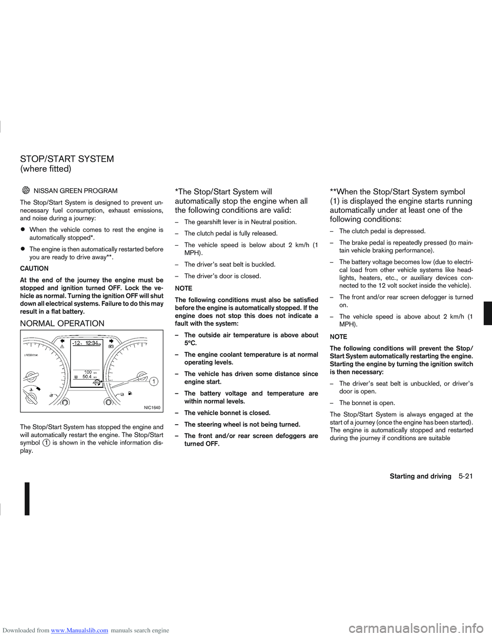
The Stop/Start System has stopped the engine and
will automatically restart the engine. The Stop/Start
symbol
j1 is shown in the vehicle information dis-
play.
*The Stop/Start System will
automatically stop the engine when all
the following conditions are valid:
– The gearshift lever is in Neutral position.
– The clutch pedal is fully released.
– The vehicle speed is below about 2 km/h (1 MPH).
– The driver’s seat belt is buckled.
– The driver’s door is closed.
NOTE
The following conditions must also be satisfied
before the engine is automatically stopped. If the
engine does not stop this does not indicate a
fault with the system:
– The outside air temperature is above about 5ºC.
– The engine coolant temperature is at normal operating levels.
– The vehicle has driven some distance since engine start.
– The battery voltage and temperature are within normal levels.
– The vehicle bonnet is closed.
– The steering wheel is not being turned.
– The front and/or rear screen defoggers are turned OFF.
**When the Stop/Start System symbol
(1) is displayed the engine starts running
automatically under at least one of the
following conditions:
– The clutch pedal is depressed.
– The brake pedal is repeatedly pressed (to main-tain vehicle braking performance).
– The battery voltage becomes low (due to electri- cal load from other vehicle systems like head-
lights, heaters, etc., or auxiliary devices con-
nected to the 12 volt socket inside the vehicle).
– The front and/or rear screen defogger is turned on.
– The vehicle speed is above about 2 km/h (1 MPH).
NOTE
The following conditions will prevent the Stop/
Start System automatically restarting the engine.
Starting the engine by turning the ignition switch
is then necessary:
– The driver’s seat belt is unbuckled, or driver’s door is open.
– The bonnet is open.
The Stop/Start System is always engaged at the
start of a journey (once the engine has been started).
The engine is automatically stopped and restarted
during the journey if conditions are suitable
NIC1640
STOP/START SYSTEM
(where fitted)
Starting and driving5-21
Page 235 of 297

Downloaded from www.Manualslib.com manuals search engine Handbrake*:
Confirm that your vehicle is held securely on a fairly
steep hill with only the handbrake applied.
Seats:
Check seat position controls such as seat adjust-
ers, seatback recliner, etc. to ensure they operate
smoothly and all latches lock securely in every posi-
tion. Check that the head restraints move up and
down smoothly and the locks hold securely in all
latched positions.
Seat belts:
Check that all parts of the seat belt system (e.g.
buckles, anchors, adjusters and retractors) operate
properly and smoothly, and are installed securely.
Check the belt webbing for cuts, fraying, wear or
damage. See “Seat belts” in the “1. Safety — seats,
seat belts and supplemental restraint system” sec-
tion for further details.
Steering wheel:
Check for any change in the steering conditions,
such as excessive free play, hard steering or strange
noises.
Warning lights and audible reminders:
Make sure that all warning/indicator lights and au-
dible reminders are operating properly.
Windscreen defogger:
Check that the air comes out of the defogger outlets
properly when operating the heater or air condi-
tioner.Windscreen wiper and washer*:
Check that the wipers and washer operate properly
and that the wipers do not streak.
When performing any inspection or maintenance
work on your vehicle, always take care to prevent
serious accidental injury to yourself or damage to
the vehicle. The following are general precautions
which should be closely observed.
Park the vehicle on a level surface, apply the
handbrake securely and block the wheels to
prevent the vehicle from moving. For a manual
transmission models, move the gear lever to
N (Neutral) position.[For automatic transmis-
sion or continuously variable transmission
models: move the selector lever to P (Park)
position.]
Do not work under the engine bonnet while
the engine is hot. Turn off the engine and wait
until it cools down.
Be sure to turn the ignition switch to the “OFF”
or LOCK position.
When the ignition switch is in the ON or Acc
position, the cooling fan may start to operate
suddenly even when the engine is not run-
ning. To avoid injury, always disconnect the
negative battery cable before working near
the engine.
If you must work with the engine running,
keep your hands, clothing, hair and tools away
from moving fans, belts and any other moving
parts.
It is advisable to remove ties and any jewel-
lery, such as rings, watches, etc. before work-
ing on your vehicle.
MAINTENANCE PRECAUTIONS
8-4Maintenance and do-it-yourself
Page 257 of 297

Downloaded from www.Manualslib.com manuals search engine Only hold the xenon headlight bulb by the
base.
The bulb is manufactured from high-quality
quartz and is under high pressure.
Damage, soiling, and fingerprints should be
avoided and, if necessary, removed with alco-
hol before installing the bulb.
When the headlights are switched on, the
bulbs produce a certain amount of UV radia-
tion. In order to avoid any impairment of health
(burning and conjunctivitis), the bulb should
only be used in closed headlights with appro-
priate UV–absorbing front glass.
Due to the risk of burning, the bulb should be
left to cool down for 3 minutes after switching
off before touching.
Due to the use of mercury and various salts,
the bulb should be treated as special waste
when discarded.
The bulb may only be operated with a suitable
ballast which produces very high voltages
when switched on and during operation.
Contact with bulb and wires should therefore
be avoided and a safe distance of at least 30
mm should be maintained.
Replacing the halogen headlight bulb
CAUTION
High pressure halogen gas is sealed inside
the halogen bulb. The bulb may break if the
glass envelope is scratched or the bulb is
dropped.
When handling the bulb, DO NOT TOUCH THE
GLASS ENVELOPE.
Use the same number type and wattage as
originally installed.
Aiming is usually not necessary after replac-
ing the bulb. When aiming adjustment is nec-
essary, contact a NISSAN dealer or qualified
workshop.
Do not leave the bulb out of the headlight
reflector for a long period of time as dust,
moisture or smoke may enter the headlight
body and affect the performance of the head-
light.
The headlight is a semi-sealed beam type which
uses a replaceable headlight (halogen) bulb. A bulb
can be replaced from inside the engine compart-
ment without removing the headlight assembly.
Contact a NISSAN dealer or qualified workshop, if
you need assistance for bulb replacement.
1. Open the bonnet. For details, see “Bonnet release” in the “3. Pre-driving checks and
adjustments” section.
2. Disconnect the negative (—) battery cable. 3. When the broken bulb is located in the headlight
assembly under the air duct, carefully remove the
clips and rotate the air duct
jc clockwise a 1/4
of a turn.
4. Remove the cap (
jAorjB ) of the headlight as-
sembly.
5. Turn the connector 1/4 of a turn in the anti clock- wise direction and remove the headlight bulb.
6. Install the new bulb in the reverse order of re- moval and make sure that the cap is securely
sealed with the headlight body.
7. Where removed (step 3.), re-install the air duct
jc and clips in the order of removal.
8. Reconnect the negative (—) battery cable and close the bonnet.
NOTE
Fog may temporarily form inside the lens of the
exterior lights in the rain or in a car wash. The fog
is caused by a temperature difference between
the inside and the outside of the lens. This is not
a malfunction. If large droplets can be seen, then
contact a NISSAN dealer or qualified workshop.
8-26Maintenance and do-it-yourself
Page 258 of 297

Downloaded from www.Manualslib.com manuals search engine EXTERIOR LIGHTS
ItemWattage (W)
Headlight (Low or high beam:
type H7) 55
Front turn signal light 21
Front side light 5
Front fog light (H11 type, where
fitted) *1 55
Side turn signal light 5
Rear combination light Turn signal light 21
Stop/Tail light *1 LED
Reverse light *1 21
High-mounted stop light *1 LED
Number plate light 5
Rear fog light 21
*1: If replacement is required, contact a NISSAN dealer or qualified workshop.
INTERIOR LIGHTS
Item Wattage
(W)
Room light/Map lights (where fitted)
Foot well light (where fitted) 5
3
Room light — rear (where fitted) 5
Reading lights — rear (where fitted) 8
Luggage compartment light (where fitted) 5
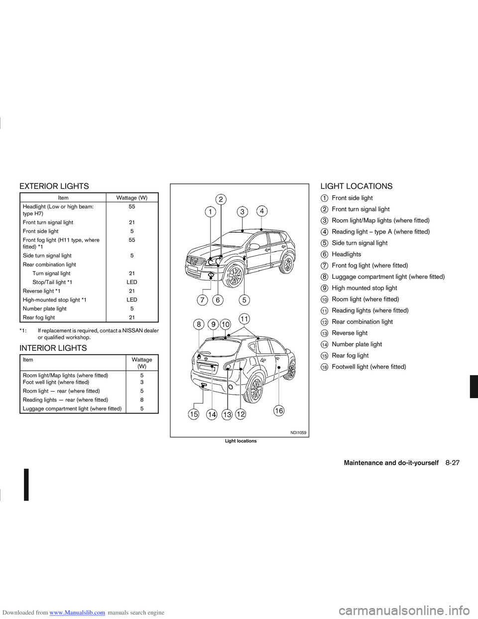
LIGHT LOCATIONS
j
1 Front side light
j2Front turn signal light
j3Room light/Map lights (where fitted)
j4Reading light – type A (where fitted)
j5Side turn signal light
j6Headlights
j7Front fog light (where fitted)
j8Luggage compartment light (where fitted)
j9High mounted stop light
j10Room light (where fitted)
j11Reading lights (where fitted)
j12Rear combination light
j13Reverse light
j14Number plate light
j15Rear fog light
j16Footwell light (where fitted)
NDI1059
Light locations
Maintenance and do-it-yourself8-27