2012 NISSAN QASHQAI Sd card
[x] Cancel search: Sd cardPage 138 of 297

Downloaded from www.Manualslib.com manuals search engine ANTI-THEFT SYSTEM
Use of a 4-digit radio PIN (Personal Identification
Number) code, known only to the vehicle owner,
effectively reduces the possibility of the audio unit
being stolen. Without the PIN code the audio unit
cannot be activated.
If force is used to try and remove the audio unit, the
Anti-theft system activates and the audio unit is
locked. The only way to unlock the audio unit is to
enter the radio code number shown on an identifica-
tion card supplied with the vehicle documentation.
NOTE
The 4 digit radio code is shown on a card that
you received with your vehicle documenta-
tion.
Record the 4 digit radio code on the “Security
information” page at the end of this manual.
Remove the security page and keep it in a
safe, not in the vehicle.
Contact a NISSAN dealer if you do lose the 4
digit radio code of the audio unit.
Unlocking the unit
If the battery supply to the vehicle is interrupted, the
audio unit will lock.
When the power is restored and the unit switched
on, the display will show [Radio Code:] and it will be
unlocked when the codes have been entered cor-
rectly.
Unlocking procedure:
Read this section very carefully. It is important
that the instructions are followed precisely.
To unlock the audio unit, proceed as follows:
1. Turn the ignition switch to the Acc or ON posi-tion.
2. [Radio Code:] is displayed along with four nu- merical zero digits.
3. Press preset button
j1 the number of times cor-
responding with the first digit of the radio code. For example, if the radio code is 5169: for the
first digit, “5”, press the preset button
j1 five
times.
4. The second, third, and fourth digits of the radio code must be entered, in the same way, only
now using preset buttons
j2,j3 , andj4.
For example, press
j2 once,j3 six times, andj4 nine times.
5. Press with a long press preset button <
j6>to
confirm the code. If you entered the code cor-
rectly the unit will switch on.
6. If the code is entered incorrectly a notification message [INCORRECT PIN] and the number of
attempts left [REMAINING TRIES: XX] will be
shown.
After reading the message, press the
button to return to the entry screen and enter the
correct radio code.
– If the wrong code is entered after the third attempt, the audio unit will lock for 60 min-
utes. The display will show a count down timer
from 60 to 0 (minutes). After 60 minutes enter
the correct radio code.
– If the wrong code is entered after eight sets of three entries, the audio unit will lock per-
manently. Contact a NISSAN dealer for fur-
ther details.
AUDIO MAIN OPERATION
The audio unit operates when the ignition switch is
in Acc or ON position.
NAA1217
Display screen, heater and air conditioner, and audio system4-31
Page 199 of 297

Downloaded from www.Manualslib.com manuals search engine steep slope consider the incline (the towing
weights quoted are for a 12% slope).
Follow the trailer manufacturer’s instructions.
Have your vehicle serviced more often than at
the intervals specified in the separately provided
Warranty Information and Maintenance booklet.
Trailer towing requires more fuel than under nor-
mal circumstances because of a considerable
increase in traction power required and resis-
tance.
When towing a trailer, observe the following re-
stricted towing speed:
Speed: below 100 km/h (62 MPH)
CAUTION
While towing a trailer, check the engine coolant
temperature gauge regularly to prevent engine
overheating.
TYRE PRESSURE
When towing a trailer, inflate the vehicle tyres to the
maximum recommended COLD tyre pressure, as
indicated on the tyre placard (for full loading). Make
sure the trailer tyre pressures are correct.
CAUTION
Do not tow a trailer when the vehicle is installed
with a temporary-use spare tyre.
SAFETY CHAINS
Always use a suitable chain between the vehicle
and trailer. The chain should be attached to the hitch
and not to the vehicle bumper or axle. Be sure to
leave enough slack in the chain to permit turning
corners. The chain should not drag on the ground:
passing the chain across the trailer hitch may be the
best practice depending on your trailer.
TRAILER BRAKES
Ensure that trailer brakes are installed as required
by local regulations. Also check that all other trailer
equipment conforms to local regulations.
TRAILER DETECTION (where fitted)
When towing a trailer and the turn signal switch is
used, the electrical system of the vehicle will detect
an additional electrical load of the trailer lighting. As
a result, the trailer direction indicator light comes
on.
INSTALLATION OF COUPLING
DEVICE
NISSAN recommends that the coupling device for
trailer towing be installed under the following condi-
tions:
Maximum permissible vertical load on the cou-
pling device: 736 N (75 kg, 165 lb)
The coupling device, mounting points and instal-
lation parts on your vehicle: as shown as an ex-
ample in the illustration. Follow all of the coupling device manufacturer’s in-
structions for installation and use.
5-36Starting and driving
Page 202 of 297
Downloaded from www.Manualslib.com manuals search engine The brake system has two separate hydraulic cir-
cuits. If one circuit malfunctions, you will still have
braking ability with two wheels.
BRAKE PRECAUTIONS
Vacuum assisted brake
The brake booster aids braking by using engine
vacuum. If the engine stops or the drive belt is bro-
ken, you can stop the vehicle by depressing the
brake pedal. However, greater foot pressure on the
brake pedal will be required to stop the vehicle and
the stopping distance will be longer.
Wet brakes
When the vehicle is washed or driven through wa-
ter, the brakes may get wet. As a result, your brak-
ing distance will be longer and the vehicle may pull
to one side during braking.
To dry brakes, drive the vehicle at a safe speed
while lightly pressing the brake pedal to heat up the
brakes. Do this until the brakes return to normal.
Avoid driving the vehicle at high speeds until the
brakes function correctly.
Using the brakes
Avoid resting your foot on the brake pedal while
driving. This will overheat the brakes, wear out the
brake linings and pads faster and reduce fuel
economy performance.
To help reduce brake wear and to prevent the brakes
from overheating, reduce speed and downshift to a
lower gear before going down a slope or long down-hill gradient. Overheated brakes may reduce brak-
ing performance and could result in loss of vehicle
control.
CAUTION
While driving on a slippery surface, be careful
when braking, accelerating or downshifting.
Abrupt braking actions or sudden acceleration
could cause the wheels to skid and result in an
accident.
Be aware that brakes will fade if repeated heavy
brake applications are made.
Driving uphill
When starting on a steep gradient, it is sometimes
difficult to operate the brake (AT or CVT models) or
both the brake and clutch (MT models). Use the
handbrake to hold the vehicle. Do not slip the clutch
(MT models). When ready to start, slowly release
the handbrake while depressing the accelerator
pedal and releasing the clutch (MT models) or de-
pressing the accelerator pedal (AT or CVT models).
Driving downhill
The engine braking action is effective for controlling
the vehicle while descending hills.
The gear lever (MT models) should be placed in a
gear position low enough to obtain sufficient engine
braking.
For the AT or CVT models, a low gear position in
the manual shift mode, low enough to obtain suffi-
cient engine braking, should be selected.
ANTI-LOCK BRAKING SYSTEM (ABS)
WARNING
The Anti-lock Braking System (ABS) is a so-
phisticated device, but it cannot prevent acci-
dents resulting from careless or dangerous
driving techniques. It can help maintain ve-
hicle control during braking on slippery sur-
faces. Remember that stopping distances
may also be longer on rough, gravel or snow
covered roads, or if you are using snow
chains. Always maintain a safe distance from
the vehicle in front of you. Ultimately, the
driver is responsible for safety.
Tyre type and condition may also affect brak-
ing effectiveness.
– When replacing tyres, install the specified
size of tyres on all four wheels.
– When installing a spare tyre, make sure it is the proper size and type as specified on
the tyre placard. See “Vehicle
identification” in the “9. Technical
information” section for the tyre placard
location.
– For detailed information, see “Wheels and tyres” in the “8. Maintenance and
do-it-yourself” section.
The Anti-lock Braking System (ABS) controls the
brakes so that the wheels do not lock during hard
braking or when braking on slippery surfaces. The
system detects the rotation speed at each wheel
BRAKE SYSTEM
Starting and driving5-39
Page 209 of 297
Downloaded from www.Manualslib.com manuals search engine TEMPORARY-USE SPARE TYRE
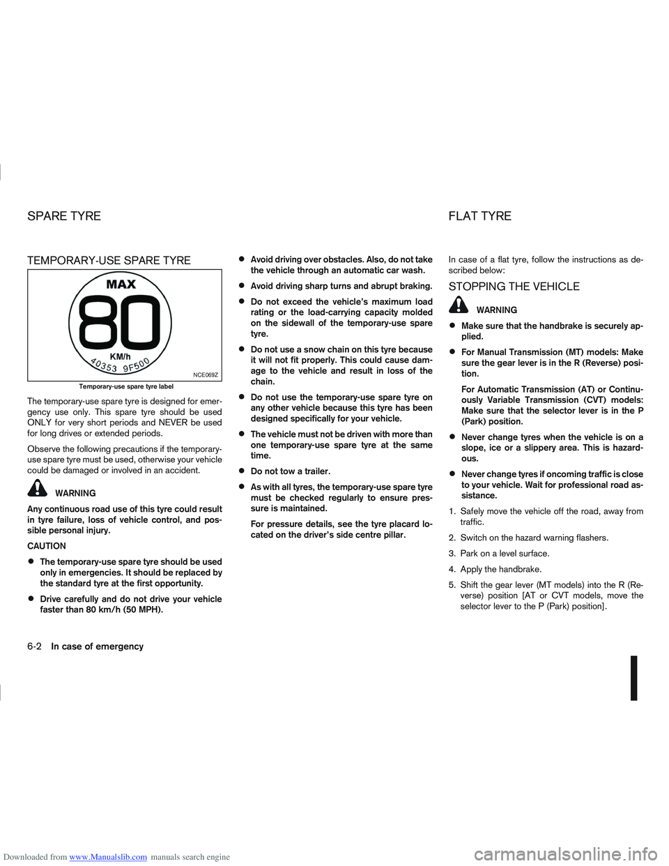
The temporary-use spare tyre is designed for emer-
gency use only. This spare tyre should be used
ONLY for very short periods and NEVER be used
for long drives or extended periods.
Observe the following precautions if the temporary-
use spare tyre must be used, otherwise your vehicle
could be damaged or involved in an accident.
WARNING
Any continuous road use of this tyre could result
in tyre failure, loss of vehicle control, and pos-
sible personal injury.
CAUTION
The temporary-use spare tyre should be used
only in emergencies. It should be replaced by
the standard tyre at the first opportunity.
Drive carefully and do not drive your vehicle
faster than 80 km/h (50 MPH).
Avoid driving over obstacles. Also, do not take
the vehicle through an automatic car wash.
Avoid driving sharp turns and abrupt braking.
Do not exceed the vehicle’s maximum load
rating or the load-carrying capacity molded
on the sidewall of the temporary-use spare
tyre.
Do not use a snow chain on this tyre because
it will not fit properly. This could cause dam-
age to the vehicle and result in loss of the
chain.
Do not use the temporary-use spare tyre on
any other vehicle because this tyre has been
designed specifically for your vehicle.
The vehicle must not be driven with more than
one temporary-use spare tyre at the same
time.
Do not tow a trailer.
As with all tyres, the temporary-use spare tyre
must be checked regularly to ensure pres-
sure is maintained.
For pressure details, see the tyre placard lo-
cated on the driver’s side centre pillar. In case of a flat tyre, follow the instructions as de-
scribed below:
STOPPING THE VEHICLE
WARNING
Make sure that the handbrake is securely ap-
plied.
For Manual Transmission (MT) models: Make
sure the gear lever is in the R (Reverse) posi-
tion.
For Automatic Transmission (AT) or Continu-
ously Variable Transmission (CVT) models:
Make sure that the selector lever is in the P
(Park) position.
Never change tyres when the vehicle is on a
slope, ice or a slippery area. This is hazard-
ous.
Never change tyres if oncoming traffic is close
to your vehicle. Wait for professional road as-
sistance.
1. Safely move the vehicle off the road, away from traffic.
2. Switch on the hazard warning flashers.
3. Park on a level surface.
4. Apply the handbrake.
5. Shift the gear lever (MT models) into the R (Re- verse) position [AT or CVT models, move the
selector lever to the P (Park) position].
NCE069Z
Temporary-use spare tyre label
SPARE TYRE FLAT TYRE
6-2In case of emergency
Page 212 of 297

Downloaded from www.Manualslib.com manuals search engine Never allow passengers to stay in the vehicle
while it is on the jack.
Remove all loads before lifting the vehicle with
the jack.
Make sure to block the wheel diagonally op-
posite the flat tyre as described earlier in this
section.
CAUTION
The jack should be used on firm, level ground.
1. Place the jack directly under the jack-up point as illustrated so that the top of the jack contacts the
vehicle at the jack-up point.
2. Align the centre of both the jack head and the notches at the jack-up point as shown.
3. Fit the groove of the jack head between the two notches as shown. 4. Loosen each wheel nut by one or two turns
anticlockwise with the wheel wrench.
Do not remove the wheel nuts until the tyre is
off the ground.
Models with wheel lock nuts (where fitted):
If the wheel is equipped with a wheel lock nut,
insert the wheel lock key
j1 and loosen it as pre-
viously described.
The wheel lock nut can only be removed with the
wheel lock key. A key number is necessary if you
need to duplicate the wheel lock key.
Record the key number as shown on the key
code card on the “Security information” page at
the end of this manual and keep it in a safe place,
not in the vehicle. If you loose the wheel lock key,
see your NISSAN dealer for a duplicate with the
original wheel lock key code. Make sure to keep the lock key in the vehicle.
Otherwise, wheels cannot be removed and the
service cannot be performed.
5. To lift the vehicle, securely hold and turn the handle clockwise as shown.
6. Carefully raise the vehicle until the tyre clears the ground.
7. Remove the wheel nuts, then remove the wheel with the flat tyre.NCE256Z
Jack-up points
NCE143Z
NCE309
5–seater
NCE308
7–seater
In case of emergency6-5
Page 213 of 297
Downloaded from www.Manualslib.com manuals search engine CAUTION
The wheel is heavy. Be sure that your feet are
clear of the wheel and use gloves as necessary
to avoid injury.
Installing the wheel
WARNING
The temporary use spare tyre is designed for
emergency use. See “Spare tyre” earlier in
this section.
Never use wheel nuts other than those pro-
vided with your vehicle. Incorrect wheel nuts
or improperly tightened wheel nuts may cause
the wheel to become loose or come off. This
could cause an accident.
Never use oil or grease on the wheel studs or
nuts. This may cause the wheel nuts to be-
come loose.
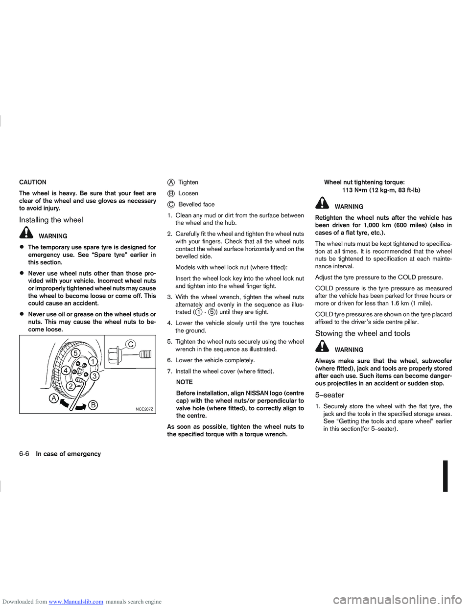
jATighten
jB Loosen
jC Bevelled face
1. Clean any mud or dirt from the surface between the wheel and the hub.
2. Carefully fit the wheel and tighten the wheel nuts with your fingers. Check that all the wheel nuts
contact the wheel surface horizontally and on the
bevelled side.
Models with wheel lock nut (where fitted):
Insert the wheel lock key into the wheel lock nut
and tighten into the wheel finger tight.
3. With the wheel wrench, tighten the wheel nuts alternately and evenly in the sequence as illus-
trated (
j1-j5 ) until they are tight.
4. Lower the vehicle slowly until the tyre touches the ground.
5. Tighten the wheel nuts securely using the wheel wrench in the sequence as illustrated.
6. Lower the vehicle completely.
7. Install the wheel cover (where fitted). NOTE
Before installation, align NISSAN logo (centre
cap) with the wheel nuts/or perpendicular to
valve hole (where fitted), to correctly align to
the centre.
As soon as possible, tighten the wheel nuts to
the specified torque with a torque wrench. Wheel nut tightening torque:
113 (12 kg-m, 83 ft-lb)
WARNING
Retighten the wheel nuts after the vehicle has
been driven for 1,000 km (600 miles) (also in
cases of a flat tyre, etc.).
The wheel nuts must be kept tightened to specifica-
tion at all times. It is recommended that the wheel
nuts be tightened to specification at each mainte-
nance interval.
Adjust the tyre pressure to the COLD pressure.
COLD pressure is the tyre pressure as measured
after the vehicle has been parked for three hours or
more or driven for less than 1.6 km (1 mile).
COLD tyre pressures are shown on the tyre placard
affixed to the driver’s side centre pillar.
Stowing the wheel and tools
WARNING
Always make sure that the wheel, subwoofer
(where fitted), jack and tools are properly stored
after each use. Such items can become danger-
ous projectiles in an accident or sudden stop.
5–seater
1. Securely store the wheel with the flat tyre, the jack and the tools in the specified storage areas.
See “Getting the tools and spare wheel” earlier
in this section(for 5–seater).NCE287Z
6-6In case of emergency
Page 214 of 297
Downloaded from www.Manualslib.com manuals search engine 2. Store the subwoofer (where fitted) as it was origi-nally installed.
3. Install the retainer and replace the floor cover.
7–seater
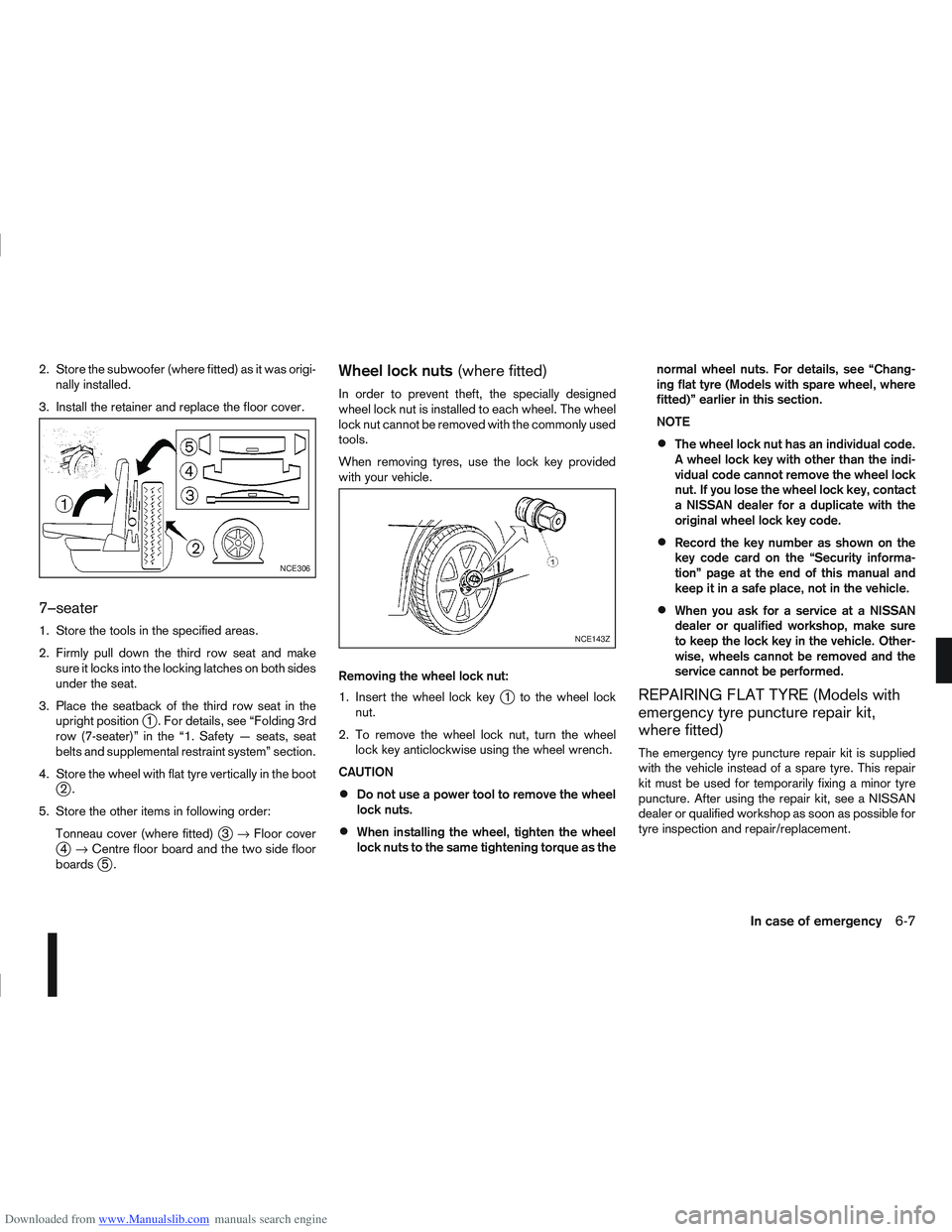
1. Store the tools in the specified areas.
2. Firmly pull down the third row seat and make sure it locks into the locking latches on both sides
under the seat.
3. Place the seatback of the third row seat in the upright position
j1 . For details, see “Folding 3rd
row (7-seater)” in the “1. Safety — seats, seat
belts and supplemental restraint system” section.
4. Store the wheel with flat tyre vertically in the boot
j2.
5. Store the other items in following order: Tonneau cover (where fitted)
j3→ Floor coverj4→ Centre floor board and the two side floor
boardsj5.
Wheel lock nuts (where fitted)
In order to prevent theft, the specially designed
wheel lock nut is installed to each wheel. The wheel
lock nut cannot be removed with the commonly used
tools.
When removing tyres, use the lock key provided
with your vehicle.
Removing the wheel lock nut:
1. Insert the wheel lock key
j1 to the wheel lock
nut.
2. To remove the wheel lock nut, turn the wheel lock key anticlockwise using the wheel wrench.
CAUTION
Do not use a power tool to remove the wheel
lock nuts.
When installing the wheel, tighten the wheel
lock nuts to the same tightening torque as the normal wheel nuts. For details, see “Chang-
ing flat tyre (Models with spare wheel, where
fitted)” earlier in this section.
NOTE
The wheel lock nut has an individual code.
A wheel lock key with other than the indi-
vidual code cannot remove the wheel lock
nut. If you lose the wheel lock key, contact
a NISSAN dealer for a duplicate with the
original wheel lock key code.
Record the key number as shown on the
key code card on the “Security informa-
tion” page at the end of this manual and
keep it in a safe place, not in the vehicle.
When you ask for a service at a NISSAN
dealer or qualified workshop, make sure
to keep the lock key in the vehicle. Other-
wise, wheels cannot be removed and the
service cannot be performed.
REPAIRING FLAT TYRE (Models with
emergency tyre puncture repair kit,
where fitted)
The emergency tyre puncture repair kit is supplied
with the vehicle instead of a spare tyre. This repair
kit must be used for temporarily fixing a minor tyre
puncture. After using the repair kit, see a NISSAN
dealer or qualified workshop as soon as possible for
tyre inspection and repair/replacement.
NCE306
NCE143Z
In case of emergency6-7
Page 216 of 297
Downloaded from www.Manualslib.com manuals search engine Repairing tyre
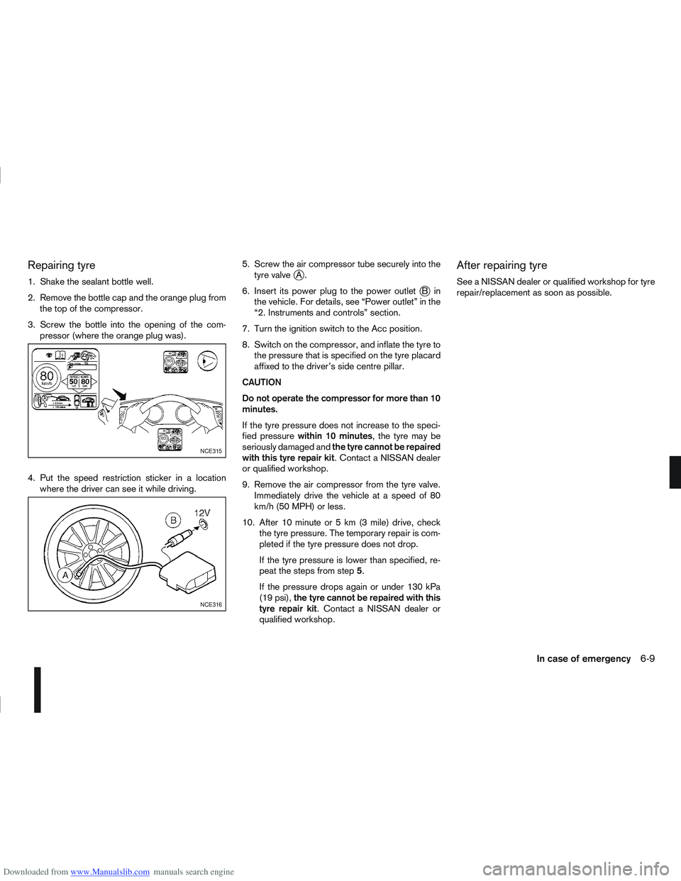
1. Shake the sealant bottle well.
2. Remove the bottle cap and the orange plug fromthe top of the compressor.
3. Screw the bottle into the opening of the com- pressor (where the orange plug was).
4. Put the speed restriction sticker in a location where the driver can see it while driving. 5. Screw the air compressor tube securely into the
tyre valvejA.
6. Insert its power plug to the power outlet
jBin
the vehicle. For details, see “Power outlet” in the
“2. Instruments and controls” section.
7. Turn the ignition switch to the Acc position.
8. Switch on the compressor, and inflate the tyre to the pressure that is specified on the tyre placard
affixed to the driver’s side centre pillar.
CAUTION
Do not operate the compressor for more than 10
minutes.
If the tyre pressure does not increase to the speci-
fied pressure within 10 minutes , the tyre may be
seriously damaged and the tyre cannot be repaired
with this tyre repair kit . Contact a NISSAN dealer
or qualified workshop.
9. Remove the air compressor from the tyre valve. Immediately drive the vehicle at a speed of 80
km/h (50 MPH) or less.
10. After 10 minute or 5 km (3 mile) drive, check the tyre pressure. The temporary repair is com-
pleted if the tyre pressure does not drop.
If the tyre pressure is lower than specified, re-
peat the steps from step 5.
If the pressure drops again or under 130 kPa
(19 psi), the tyre cannot be repaired with this
tyre repair kit. Contact a NISSAN dealer or
qualified workshop.
After repairing tyre
See a NISSAN dealer or qualified workshop for tyre
repair/replacement as soon as possible.
NCE315
NCE316
In case of emergency6-9