2012 NISSAN NOTE Instruments
[x] Cancel search: InstrumentsPage 81 of 235

FUEL FILLER LID OPENER LEVER
A.LHD models
B.RHD models
To open the fuel filler lid, pull up the opener lever
j1 . To lock, close the fuel filler lid securely.
FUEL FILLER CAP
The fuel filler cap is a ratcheting type. Tighten the
cap clockwise until ratcheting clicks are heard.Put the fuel filler cap on the cap holder
j1 while
refuelling.
WARNING
•Fuel is extremely flammable and highly explo-
sive under certain conditions. Always stop the
engine and do not smoke or allow open flames
or sparks near the vehicle when refuelling.
•Fuel may be under pressure. Turn the cap half
a turn and wait for any hissing sound to stop,
in order to prevent fuel from spraying out and
causing possible personal injury.
•Use only a NISSAN fuel filler cap or exact
equivalent as a replacement. It has a built-in
safety valve needed for proper operation of
the fuel system and emission control system.
An incorrect cap can result in a serious mal-
function and possible injury.
CAUTION
If fuel is spilled on the vehicle body, flush it away
with water to avoid paint damage.To apply:Pull the lever up
j1.
To release:Pull the lever up slightly, push the but-
ton
j2 and lower completely.
Before driving, check that the brake warning light
goes out. For additional information, see “Warn-
ing/indicator lights and audible reminders” in the
“2. Instruments and controls” section.
NOTE
A buzzer will sound if the vehicle is driven with-
out releasing the handbrake.
NPA1013
NPA876Z
NPA728Z
FUEL FILLER LID HANDBRAKE LEVER
Pre-driving checks and adjustments3-11
Page 92 of 235

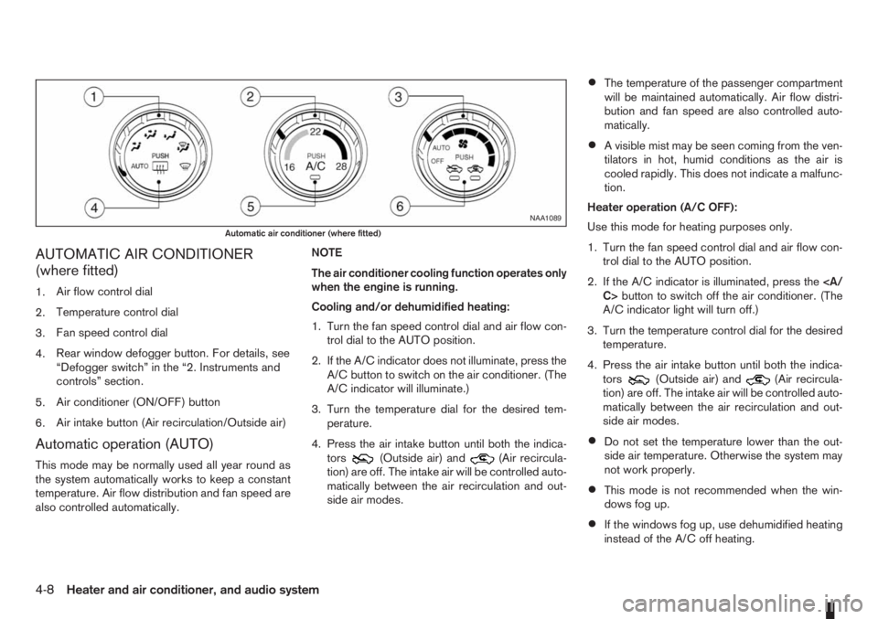
AUTOMATIC AIR CONDITIONER
(where fitted)
1.Air flow control dial
2.Temperature control dial
3.Fan speed control dial
4.Rear window defogger button. For details, see
“Defogger switch” in the “2. Instruments and
controls” section.
5.Air conditioner (ON/OFF) button
6.Air intake button (Air recirculation/Outside air)
Automatic operation (AUTO)
This mode may be normally used all year round as
the system automatically works to keep a constant
temperature. Air flow distribution and fan speed are
also controlled automatically.NOTE
The air conditioner cooling function operates only
when the engine is running.
Cooling and/or dehumidified heating:
1. Turn the fan speed control dial and air flow con-
trol dial to the AUTO position.
2. If the A/C indicator does not illuminate, press the
A/C button to switch on the air conditioner. (The
A/C indicator will illuminate.)
3. Turn the temperature dial for the desired tem-
perature.
4. Press the air intake button until both the indica-
tors(Outside air) and(Air recircula-
tion) are off. The intake air will be controlled auto-
matically between the air recirculation and out-
side air modes.
•The temperature of the passenger compartment
will be maintained automatically. Air flow distri-
bution and fan speed are also controlled auto-
matically.
•A visible mist may be seen coming from the ven-
tilators in hot, humid conditions as the air is
cooled rapidly. This does not indicate a malfunc-
tion.
Heater operation (A/C OFF):
Use this mode for heating purposes only.
1. Turn the fan speed control dial and air flow con-
trol dial to the AUTO position.
2. If the A/C indicator is illuminated, press the
C>button to switch off the air conditioner. (The
A/C indicator light will turn off.)
3. Turn the temperature control dial for the desired
temperature.
4. Press the air intake button until both the indica-
tors
(Outside air) and(Air recircula-
tion) are off. The intake air will be controlled auto-
matically between the air recirculation and out-
side air modes.
•Do not set the temperature lower than the out-
side air temperature. Otherwise the system may
not work properly.
•This mode is not recommended when the win-
dows fog up.
•If the windows fog up, use dehumidified heating
instead of the A/C off heating.
NAA1089
Automatic air conditioner (where fitted)
4-8Heater and air conditioner, and audio system
Page 123 of 235

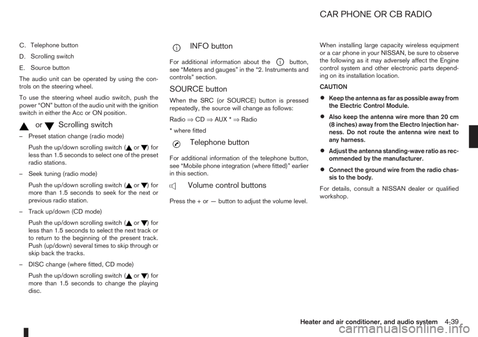
C.Telephone button
D.Scrolling switch
E.Source button
The audio unit can be operated by using the con-
trols on the steering wheel.
To use the steering wheel audio switch, push the
power “ON” button of the audio unit with the ignition
switch in either the Acc or ON position.
mormScrolling switch
– Preset station change (radio mode)
Push the up/down scrolling switch (
or) for
less than 1.5 seconds to select one of the preset
radio stations.
– Seek tuning (radio mode)
Push the up/down scrolling switch (
or) for
more than 1.5 seconds to seek for the next or
previous radio station.
– Track up/down (CD mode)
Push the up/down scrolling switch (
or) for
less than 1.5 seconds to select the next track or
to return to the beginning of the present track.
Push (up/down) several times to skip through or
skip back the tracks.
– DISC change (where fitted, CD mode)
Push the up/down scrolling switch (
or) for
more than 1.5 seconds to change the playing
disc.
mINFO button
For additional information about thebutton,
see “Meters and gauges” in the “2. Instruments and
controls” section.
SOURCE button
When the SRC (or SOURCE) button is pressed
repeatedly, the source will change as follows:
Radio⇒CD⇒AUX *⇒Radio
* where fitted
mTelephone button
For additional information of the telephone button,
see “Mobile phone integration (where fitted)” earlier
in this section.
mVolume control buttons
Press the + or — button to adjust the volume level.When installing large capacity wireless equipment
or a car phone in your NISSAN, be sure to observe
the following as it may adversely affect the Engine
control system and other electronic parts depend-
ing on its installation location.
CAUTION
•Keep the antenna as far as possible away from
the Electric Control Module.
•Also keep the antenna wire more than 20 cm
(8 inches) away from the Electro Injection har-
ness. Do not route the antenna wire next to
any harness.
•Adjust the antenna standing-wave ratio as rec-
ommended by the manufacturer.
•Connect the ground wire from the radio chas-
sis to the body.
For details, consult a NISSAN dealer or qualified
workshop.
CAR PHONE OR CB RADIO
Heater and air conditioner, and audio system4-39
Page 132 of 235

CAUTION
•Make sure you carry the Intelligent Key with
you when operating the vehicle.
•Never leave the Intelligent Key inside the ve-
hicle when you leave the vehicle.
•If the Intelligent Key is too far away from the
driver, the vehicle may not start.
MANUAL TRANSMISSION
The ignition lock is designed so that the knob can
ONLY be turned to the LOCK position when the
PUSH release button has first been depressed.
NOTE
•The ignition knob warning light () blinks
and the buzzer sounds twice when the igni-
tion knob is turned to the “OFF” position. De-
press the PUSH release button
j2 , then turn
the ignition knob to the LOCK position. See
“Warning/indicator lights and audible
reminders” in the “2. Instruments and
controls” section for further details regarding
the functionality of the ignition knob warning
light.
•When the emergency key is being used, the
PUSH release buttonj2 must be depressed
in order to turn the ignition knob to the LOCK
position although the ignition knob warning
light (
) will not blink and the buzzer will not
sound.
AUTOMATIC TRANSMISSION
The ignition knob is designed so that it cannot be
turned to the LOCK position until the selector lever
is moved to the P (Park) position. The selector lever
can only be moved from the P (Park) position when
the ignition knob is in the ON position and the
footbrake pedal is depressed.
NOTE
The ignition knob warning light (
) blinks and a
buzzer sounds twice when the ignition knob is
turned to the “OFF” position. Make sure that the
selector lever is in the P (Park) position, then turn
the ignition knob to the LOCK position. See
“Warning/indicator lights and audible reminders”
in the “2. Instruments and controls” section for
further details regarding the functionality of the
ignition knob warning light.
STEERING LOCK
To lock the steering wheel
In the LOCK position, turn the steering wheel 1/6 of
a turn from the straight up position.
To unlock the steering wheel
Depress the brake pedal, push the ignition knob and
turn it towards the Acc position while gently rotating
the steering wheel right or left.
IGNITION KNOB POSITION
LOCK (Normal parking position) (0)
The steering lock can be only be locked from this
position.
“OFF” (1)
The engine can be turned off without locking the
steering wheel.
Acc (Accessories) (2)
This position activates electrical accessories, such
as the radio, when the engine is not running.
ON (Normal operating position) (3)
This position turns on the ignition system and the
electrical accessories.
START (4)
The engine starter activates and the engine will start.
As soon as the engine has started, release the knob
immediately. It will return to the ON position.
5-8Starting and driving
Page 151 of 235

WARNING
•If the Electrically Power Assisted Steering
warning light (EPAS) illuminates while driv-
ing, the power assist for steering will be dis-
abled. Greater steering efforts are required to
operate the steering wheel, especially in
sharp turns and at low speed. Stop the ve-
hicle as soon as safely possible and contact a
NISSAN dealer or qualified workshop for fur-
ther assistance.
•In certain circumstances, factors external to
the EPAS system may contribute to the illumi-
nation of the warning light. If the warning light
illuminates, stop the vehicle as soon as safely
possible if driving. Turn the ignition switch to
the “OFF” position and wait for approximately
20 seconds, then turn the ignition switch to
the ON position again. If the light remains illu-
minated, we recommend you to contact a
NISSAN dealer or qualified workshop. See
“Warning/indicator lights and audible
reminders” in the “2. Instruments and
controls” section for further details regarding
the EPAS warning light.
The EPAS (Electrically Power Assisted Steering)
system is designed to assist steering.
The steering may appear to feel slightly stiff follow-
ing parking manoeuvres including a great deal of
steering. This is not a malfunction; it is caused by a
control system designed to prevent the motor fromoverheating. No servicing is required. The EPAS
system will return to normal operation the next time
the vehicle is driven.
Similarly, the EPAS system may not provide full as-
sistance during periods of reduced battery voltage
but will recover once normal battery voltage is re-
stored.
If the EPAS warning light comes on while the engine
is running, it may indicate that the EPAS system is
not working properly. As result greater steering ef-
forts are required to steer the steering wheel, espe-
cially in sharp turns and at low speeds. Have the
system checked by a NISSAN dealer or qualified
workshop as soon as possible.
NOTE
Incorrectly inflated tyres can lead to poor steer-
ing ability and make the driver suspect a steering
problem: keep the vehicle’s tyres inflated to the
correct pressure at all times.
CAUTION
Any malfunction or accident that could have dam-
aged the steering components (including actual
or attempted theft damage) should be reported
to a NISSAN dealer or qualified workshop.The brake system has two separate hydraulic cir-
cuits. If one circuit malfunctions, you will still have
braking ability with two wheels.
BRAKE PRECAUTIONS
Vacuum assisted brake
The brake booster aids braking by using engine
vacuum. If the engine stops or the drive belt is bro-
ken, you can stop the vehicle by depressing the
brake pedal. However, greater foot pressure on the
brake pedal will be required to stop the vehicle and
the stopping distance will be longer.
Wet brakes
When the vehicle is washed or driven through wa-
ter, the brakes may get wet. As a result, your brak-
ing distance will be longer and the vehicle may pull
to one side during braking.
To dry brakes, drive the vehicle at a safe speed
while lightly pressing the brake pedal to heat up the
brakes. Do this until the brakes return to normal.
Avoid driving the vehicle at high speeds until the
brakes function correctly.
Using the brakes
Avoid resting your foot on the brake pedal while
driving. This will overheat the brakes, wear out the
brake linings and pads faster and reduce fuel
economy performance.
To help reduce brake wear and to prevent the brakes
from overheating, reduce speed and downshift to a
lower gear before going down a slope or long down-
POWER STEERING SYSTEM BRAKE SYSTEM
Starting and driving5-27
Page 153 of 235

Normal operation
The ABS will not initiate at speeds below 5 to 10
km/h (3 to 6 MPH). The speeds will vary according
to road conditions.
When the ABS senses that one or more wheels are
close to locking up, the actuator rapidly applies and
releases hydraulic pressure. This action is similar to
pumping the brakes very quickly. You may feel a
pulsation in the brake pedal and hear a noise from
the actuator under the bonnet when it is operating.
This is normal and indicates that the ABS is working
properly. However, the pulsation may indicate that
road conditions are hazardous and extra care is re-
quired while driving.When accelerating, driving on slippery surfaces or
suddenly avoiding obstacles on roads, the vehicle
might swerve or slip. The Electronic Stability Pro-
gramme (ESP) system continuously monitors and
compares the driver’s intended speed and the travel
direction. The system adjusts wheel brake pressure
and engine torque to assist in improving vehicle sta-
bility.
•When the ESP system is operating, the “SLIP”
indicator light () in the combination meter
blinks.
•When only the traction control (TCS) system in
the ESP system is operating, the “SLIP” indica-
tor light (
) in the combination meter will also
blink.
•If the “SLIP” indicator light () blinks, the
road conditions are slippery. Be sure to drive
carefully. See “Warning/indicator lights and au-
dible reminders” in the “2. Instruments and
controls” section.
•Indicator light
If a malfunction occurs in the system, the “SLIP”
indicator light (
) and the ESP indicator light
() come on in the combination meter.
As long as these indicator lights are on, the trac-
tion control function is cancelled.
The ESP system uses Active Brake Limited Slip
(ABLS) system to improve vehicle traction. The Ac-
tive Brake Limited Slip (ABLS) system works when
one of the driving wheels is spinning on a slipperysurface. The Active Brake Limited Slip (ABLS) sys-
tem, brakes the spinning wheel to distribute the driv-
ing power to the other driving wheel.
If the vehicle is operated with the ESP system turned
off, all ESP and TCS functions will be turned off.
The Active Brake Limited Slip (ABLS) system and
ABS will still operate with the ESP system off. If the
Active Brake Limited Slip (ABLS) system or the ABS
is activated, the “SLIP” indicator light (
) will
blink and you may hear a clunk noise and/or feel a
pulsation in the brake pedal. This is normal and does
not indicate a malfunction.
While the ESP system is operating, you may feel a
pulsation in the brake pedal and hear a noise or
vibration from under the bonnet. This is normal and
indicates that the ESP system is working properly.
The ESP computer has a built in diagnostic feature
that tests the system each time the engine is started
and the vehicle moves forwards or reverses at a
slow speed. When the self-test occurs, you may
hear a clunk noise and/or feel a pulsation in the
brake pedal. This is normal and is not an indication
of a malfunction.
WARNING
•The ESP system is designed to help improve
driving stability but does not prevent accidents
caused by abrupt steering operation at high
speeds, or careless or dangerous driving
techniques. Reduce vehicle speed and be es-
pecially careful when driving and cornering on
slippery surfaces. Always drive carefully.
ELECTRONIC STABILITY PROGRAMME (ESP) SYSTEM (where fitted)
Starting and driving5-29
Page 164 of 235

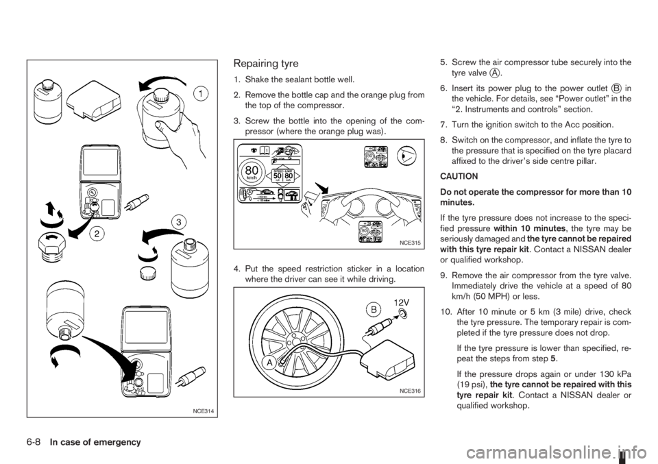
Repairing tyre
1. Shake the sealant bottle well.
2. Remove the bottle cap and the orange plug from
the top of the compressor.
3. Screw the bottle into the opening of the com-
pressor (where the orange plug was).
4. Put the speed restriction sticker in a location
where the driver can see it while driving.5. Screw the air compressor tube securely into the
tyre valvejA.
6. Insert its power plug to the power outlet
jBin
the vehicle. For details, see “Power outlet” in the
“2. Instruments and controls” section.
7. Turn the ignition switch to the Acc position.
8. Switch on the compressor, and inflate the tyre to
the pressure that is specified on the tyre placard
affixed to the driver’s side centre pillar.
CAUTION
Do not operate the compressor for more than 10
minutes.
If the tyre pressure does not increase to the speci-
fied pressurewithin 10 minutes, the tyre may be
seriously damaged andthe tyre cannot be repaired
with this tyre repair kit. Contact a NISSAN dealer
or qualified workshop.
9. Remove the air compressor from the tyre valve.
Immediately drive the vehicle at a speed of 80
km/h (50 MPH) or less.
10. After 10 minute or 5 km (3 mile) drive, check
the tyre pressure. The temporary repair is com-
pleted if the tyre pressure does not drop.
If the tyre pressure is lower than specified, re-
peat the steps from step5.
If the pressure drops again or under 130 kPa
(19 psi),the tyre cannot be repaired with this
tyre repair kit. Contact a NISSAN dealer or
qualified workshop.
NCE314
NCE315
NCE316
6-8In case of emergency