2012 NISSAN NOTE ECU
[x] Cancel search: ECUPage 40 of 235

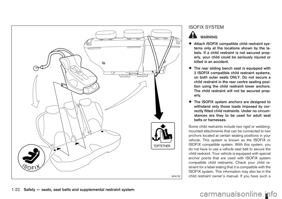
ISOFIX SYSTEM
WARNING
•Attach ISOFIX compatible child restraint sys-
tems only at the locations shown by the la-
bels. If a child restraint is not secured prop-
erly, your child could be seriously injured or
killed in an accident.
•The rear sliding bench seat is equipped with
2 ISOFIX compatible child restraint systems,
on both outer seats ONLY. Do not secure a
child restraint in the rear centre seating posi-
tion using the child restraint lower anchors.
The child restraint will not be secured prop-
erly.
•The ISOFIX system anchors are designed to
withstand only those loads imposed by cor-
rectly fitted child restraints. Under no circum-
stances are they to be used for adult seat
belts or harnesses.
Some child restraints include two rigid or webbing-
mounted attachments that can be connected to two
anchors located at certain seating positions in your
vehicle. This system is known as the ISOFIX or
ISOFIX compatible system. With this system, you
do not have to use a vehicle seat belt to secure the
child restraint. Your vehicle is equipped with special
anchor points that are used with ISOFIX system
compatible child restraints. Check your child re-
straint for a label stating that it is compatible with the
ISOFIX system. This information may also be in the
child restraint owner’s manual. If you have such a
NPA720
1-22Safety — seats, seat belts and supplemental restraint system
Page 41 of 235

child restraint, refer to the illustration for the rear
seating positions equipped with ISOFIX system an-
chors which can be used to secure the child re-
straint.
The ISOFIX system anchors are located at the rear
of the seat cushion near the seatback (as illustrated).
Labels are attached to the seat cushion to help you
locate the ISOFIX system anchors.
CAUTION
•The child restraint may also require the use of
a top tether strap. See “Top tether strap for
child restraint” later in this section for instal-
lation instructions. Alternatively, the child re-
straint may require an anti-rotation device
such as support leg. Refer to the child re-
straint system manufacturer’s instructions.
•When installing a child restraint, carefully read
and follow the instructions in this manual and
those supplied with the child restraint.
When you install an ISOFIX system compatible child
restraint to the lower anchor attachments in the rear
seat, follow these steps.
Inspect the lower anchors by inserting your fingers
into the lower anchor area and feeling to make sure
there are no obstructions over the ISOFIX system
anchors, such as seat belt webbing or seat cushion
material. The child restraint will not be secured prop-
erly if the ISOFIX system anchors are obstructed.
1. To install the ISOFIX system compatible child
restraint, insert the child restraint ISOFIX systemanchor attachments into the anchor points on the
rear seat. See “Top tether strap for child
restraint” later in this section for top tether strap
installation instructions.
2. Fit the ISOFIX funnel guides (supplied with the
ISOFIX child seat – where fitted) to the vehicle
ISOFIX brackets located at the base of the rear
outer seat cushions (refer to the ISOFIX label for
appropriate locations).
3. After attaching the child restraint and before plac-
ing the child in it, use force to tilt the child re-
straint from side to side and tug it forward to
make sure that the child restraint is securely held
in place. Make sure that both ISOFIX anchor-
ages have latched correctly.
4. Check to make sure that the child restraint is
properly secured prior to each use.
NOTE
•For forward facing ISOFIX child restraint
on the rear seat, set the rear sliding bench
seat to its rearmost position and the front
passenger seat as far forward as possible.
•For rearward facing ISOFIX child restraint
on the rear seat, slide the front passenger
seat as far backwards as possible and slide
the rear bench seat forwards until the edge
of the child restraint touches the front seat.
TOP TETHER STRAP FOR CHILD
RESTRAINT
The top tether strap of the child restraint must be
secured to the provided anchor point of your ve-
hicle.Follow the child restraint manufacturer
owner’s manual for installation instructions.
Secure the top tether strap to the anchor bracket as
illustrated.
WARNING
•The child restraint anchor points are designed
to withstand only those loads imposed by cor-
rectly fitted child restraints. Under no circum-
stances are they to be used for adult seat
belts or harnesses.
•The child restraint top tether strap may be
damaged by contact with the rear parcel shelf
or items in the luggage compartment area.
Remove the rear parcel shelf from the vehicle
or secure it in the luggage compartment area.
Also, secure any lose items in the luggage
compartment. Your child could be seriously
injured or killed in a collision if the top tether
strap is damaged.
Safety — seats, seat belts and supplemental restraint system1-23
Page 49 of 235

Air bag warning light (red)Ignition knob warning light (red)Overdrive off indicator light (AT models)
(orange)
Brake warning light (red)NATS security indicator light (red)Rear fog light indicator light (orange)
Charge warning light (red)Seat belt warning light (red)SLIP indicator light (orange)
Door open warning light (red)Intelligent Key warning light (red)/Intelligent
Key indicator light (green)Front fog light indicator light (green)
Engine coolant temperature warning light
(red – HOT)Anti-lock Braking System warning light
(orange)Side light and headlight indicator light (green)
Engine oil pressure warning light (red)Electronic Stability Programme (ESP) off
indicator light (orange)Turn signal/hazard indicator light (green)
Malfunction warning (light) and Water in fuel
filter warning light (red)/Malfunction indicator
(light) (orange)Diesel particulate filter warning light (orange)High beam indicator light (blue)
Electrically Power Assisted Steering (EPAS)
warning light (red)Glow plug indicator light (Diesel engine)
(orange)
CHECKING BULBS
With all doors closed, apply the handbrake, fasten
the seat belts and turn the ignition switch to the ON
position without starting the engine.
The following lights will come on:
,,,
The following lights (where fitted) come on briefly
and then go off:
,,(red),,,,,,,
If any light fails to come on, it may indicate a burned-
out bulb or an open circuit in the electrical system.
Have the system repaired promptly.
WARNING LIGHTS
Air bag warning light
When the ignition switch is in the ON or START
position, the air bag light will illuminate for approxi-
mately 7 seconds and then turn off. This means the
system is operational.
If any of the following conditions occur, the air bag
systems and pre-tensioner seat belt need servicingand your vehicle must be taken to the nearest
NISSAN dealer or qualified workshop.
•The air bag warning light remains on after ap-
proximately 7 seconds.
•The air bag warning light flashes intermittently.
•The air bag warning light does not come on at
all.
Unless checked and repaired, the Supplemental Re-
straint System (SRS) and/or pre-tensioner seat belt
may not function properly.
For additional details on the air bag system, see
WARNING/INDICATOR LIGHTS AND AUDIBLE REMINDERS
Instruments and controls2-7
Page 50 of 235

“Supplemental Restraint System (air bag system)”
in the “1. Safety — seats, seat belts and supple-
mental restraint system” section.
Brake warning light
This light functions for both the handbrake and the
footbrake systems.
Handbrake indicator:
The light comes on when the handbrake is applied.
Low brake fluid warning:
The light warns of a low brake fluid level in the brake
power assist unit. If the light comes on while the
engine is running and the handbrake is not applied,
stop the vehicle and perform the following:
1. Check the brake fluid level. Add brake fluid as
much as necessary. See “Brake and clutch fluid”
in the “8. Maintenance and do-it-yourself” sec-
tion.
WARNING
If the level is below the MIN mark on the brake
fluid reservoir, do not drive until the brake sys-
tem has been checked at a NISSAN dealer or
qualified workshop.
2. If the brake fluid level is correct:
Have the warning system checked by a NISSAN
dealer or qualified workshop.
WARNING
•Driving your vehicle could be dangerous.
Therefore have it towed to the nearest
NISSAN dealer or qualified workshop.
•Pressing the brake pedal with the engine
stopped and/or low brake fluid level could in-
crease your stopping distance and require
greater pedal effort as well as pedal travel.
Charge warning light
If the light comes on while the engine is running, it
may indicate that the charging system is malfunc-
tioning. Turn the engine off and check the alternator
belt. If the belt is loose, broken, missing or if the light
remains on, see a NISSAN dealer or qualified work-
shop immediately.
CAUTION
Do not continue driving if the belt is loose, bro-
ken or missing.
Door open warning light
This light comes on when any of the doors are not
closed securely while the ignition switch is in the
ON position.
Engine coolant temperature
warning light
The engine coolant temperature varies with the out-
side air temperature and driving condition.
When the ignition switch is turned to the ON posi-tion, the engine coolant temperature warning light
illuminates for a few seconds and then goes off.
This means the system is operational.
The engine coolant temperature warning light illumi-
nates when the engine coolant temperature reaches
an excessively high temperature of approximately
105 °C (221 °F).
CAUTION
•If the engine coolant temperature warning
light comes on, stop the vehicle as soon as
safely possible and contact a NISSAN dealer
or qualified workshop.
•When towing a trailer or driving uphill, reduce
the vehicle speed as soon as safely possible
to decrease the engine coolant temperature.
•If the engine overheats, continued operation
of the vehicle may seriously damage the en-
gine. See “Engine overheat” in the “6. In case
of emergency” section for immediate action
required.
WARNING
Do not remove the radiator cap while the engine
is hot. Otherwise, there is a danger of being
scalded by the coolant that is likely to erupt from
the filler.
Engine oil pressure warning light
This light warns of low engine oil pressure. If the
light flickers, comes on during normal driving, or
stays on once the engine is started, pull off the road
2-8Instruments and controls
Page 52 of 235

If the warning light remains illuminated after the en-
gine has been started, there will be no power steer-
ing assistance: the vehicle may be driven using the
mechanical steering system although it is not rec-
ommended as the effort to turn the steering wheel
will be significantly increased compared to normal
operation.
WARNING
•If the EPAS warning light illuminates while
driving, stop as soon as safely possible.
•In certain circumstances, factors external to
the EPAS system may contribute to the illumi-
nation of the warning light. If the warning light
illuminates, stop the vehicle as soon as safely
possible if driving, turn the ignition switch to
the “OFF” position for approximately 20 sec-
onds, then turn the ignition switch to the ON
position again. If the light remains illuminated,
we recommend you to contact a NISSAN
dealer or qualified workshop.
See “Power steering system” in the “5. Starting and
driving” section for further details on the EPAS sys-
tem.
Ignition knob warning light
(Intelligent Key system only)
When the ignition knob is turned to the ON position,
the ignition knob warning light illuminates for a few
seconds and then goes off. This means the system
is operational.The ignition knob warning light warns the driver of
the ignition knob position.
MT models:
The warning light blinks and the buzzer sounds twice
when the ignition knob is turned to the “OFF” posi-
tion. Depress the ignition PUSH release button, then
turn the ignition switch to the LOCK position.
AT models:
The warning light blinks and the buzzer sounds twice
when the ignition knob is turned to the “OFF” posi-
tion. Make sure the selector lever is in the P (Park)
position, then turn the ignition switch to the LOCK
position.
See “Ignition knob (where fitted)” in the “5. Starting
and driving” section for further details.
CAUTION
•The steering wheel can only be locked when
the ignition knob is in the LOCK position. Make
sure the ignition knob is in the LOCK position
before leaving the vehicle.
•The emergency key can only be removed at
the LOCK position. Make sure the ignition
knob is in the LOCK position before removing
the emergency key.
•If the ignition knob warning light comes on
while driving, contact a NISSAN dealer or
qualified workshop for repair.
NATS security indicator light
This light blinks whenever the ignition switch is in
the LOCK or Acc position. This function indicates
that your vehicle is equipped with NISSAN Anti-
Theft System (NATS)*.
If NISSAN Anti-Theft System (NATS)* is malfunc-
tioning, this light will remain on while the ignition
switch is in the ON position.
For additional information, see “NISSAN Anti-Theft
System (NATS)” later in this section.
* Immobilizer
Seat belt warning light and
chime
The light reminds the driver to fasten his/her seat
belt. The light comes on whenever the ignition switch
is turned to the ON position. It goes out whenever
the front seat belt is securely fastened. The chime
will sound unless the front seat belt is securely fas-
tened when the vehicle speed exceeds 25 km/h (15
MPH). The chime will stop after approximately 90
seconds.
NOTE
The front passenger seat belt warning light
comes on the centre console. See “Seat belt
warning lights” in the “1. Safety — seats, seat
belts and supplemental restraint system” section.
2-10Instruments and controls
Page 66 of 235

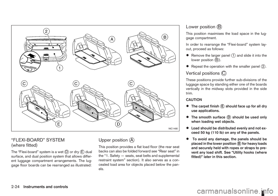
“FLEXI-BOARD” SYSTEM
(where fitted)
The “Flexi-board” system is a wetjDordryjE dual
surface, and dual position system that allows differ-
ent luggage compartment arrangements. The lug-
gage floor boards can be rearranged as illustrated:
Upper positionjA
This position provides a flat load floor (the rear seat
backs can also be folded forward see “Rear seat” in
the “1. Safety — seats, seat belts and supplemental
restraint system” section). It also serves as a con-
cealed load area for objects placed below the pan-
els.
Lower positionjB
This position maximises the load space in the lug-
gage compartment.
In order to rearrange the “Flexi-board” system lay-
out, proceed as follows:
•Remove the larger panelj1 and slide it into the
lower positionjB).
•Repeat the operation with the smaller panelj2.
Vertical positionsjC
These positions provide further sub-divisions of the
luggage space by standing either one of the boards
vertically in the midway slots provided in the side
trim.
CAUTION
•The carpet finishjE should face up for all dry
use applications.
•The smooth surfacejD should be used only
when loading wet objects.
•Load should be distributed evenly and not ex-
ceed 50 kg (110 lb) on any of the panels.
•To avoid any damage, the panels should be
placed in the lower positionjB for heavy loads
and securely held with ropes or straps to pre-
vent any load shift. See “Utility hooks (where
fitted)” later in this section.
NIC1480
2-24Instruments and controls
Page 67 of 235

WARNING
Always secure cargo with ropes or straps to help
prevent it from sliding or shifting. Do not place
cargo higher than the seatbacks. In a sudden
stop or collision, unsecured cargo could cause
personal injury.
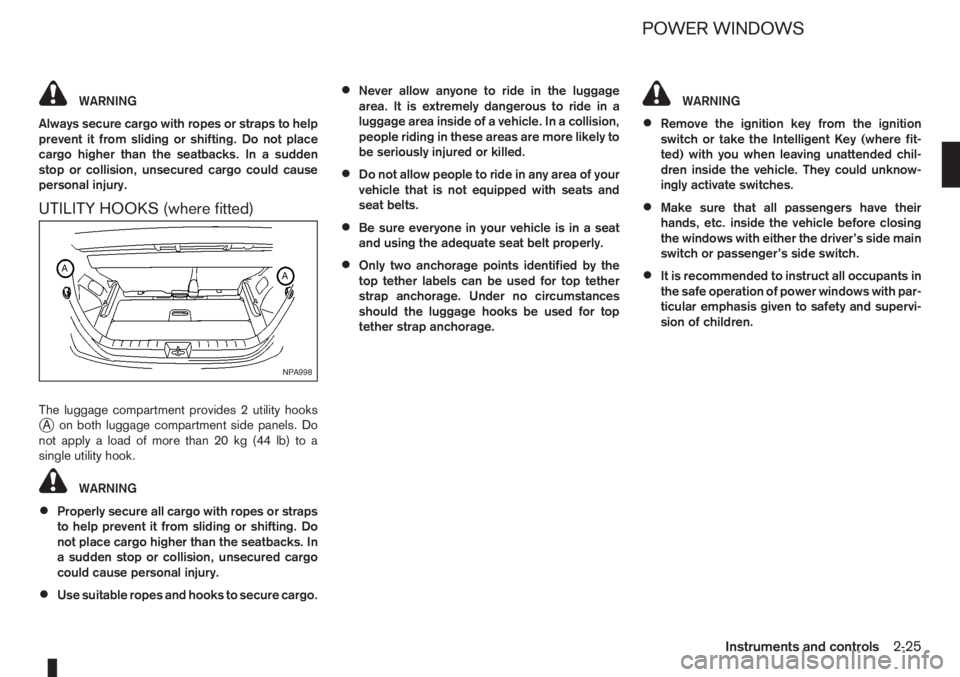
UTILITY HOOKS (where fitted)
The luggage compartment provides 2 utility hooksjA on both luggage compartment side panels. Do
notapplyaloadofmorethan20kg(44lb)toa
single utility hook.
WARNING
•Properly secure all cargo with ropes or straps
to help prevent it from sliding or shifting. Do
not place cargo higher than the seatbacks. In
a sudden stop or collision, unsecured cargo
could cause personal injury.
•Use suitable ropes and hooks to secure cargo.
•Never allow anyone to ride in the luggage
area. It is extremely dangerous to ride in a
luggage area inside of a vehicle. In a collision,
people riding in these areas are more likely to
be seriously injured or killed.
•Do not allow people to ride in any area of your
vehicle that is not equipped with seats and
seat belts.
•Be sure everyone in your vehicle is in a seat
and using the adequate seat belt properly.
•Only two anchorage points identified by the
top tether labels can be used for top tether
strap anchorage. Under no circumstances
should the luggage hooks be used for top
tether strap anchorage.
WARNING
•Remove the ignition key from the ignition
switch or take the Intelligent Key (where fit-
ted) with you when leaving unattended chil-
dren inside the vehicle. They could unknow-
ingly activate switches.
•Make sure that all passengers have their
hands, etc. inside the vehicle before closing
the windows with either the driver’s side main
switch or passenger’s side switch.
•It is recommended to instruct all occupants in
the safe operation of power windows with par-
ticular emphasis given to safety and supervi-
sion of children.
NPA998
POWER WINDOWS
Instruments and controls2-25
Page 71 of 235

3Pre-driving checks and adjustmentsPre-driving checks and adjustments
Keys ........................................................................ 3-2
Integrated keyfob/remote control system .................. 3-3
Using the remote keyless entry system ................ 3-3
Locking the doors ............................................... 3-3
Unlocking the doors – convenience mode ........... 3-4
Unlocking the doors – anti-hijack mode ............... 3-4
Switching from convenience mode to
anti-hijack mode.................................................. 3-4
Keyfob operation failure ...................................... 3-4
Intelligent Key system (where fitted) ......................... 3-5
Locking/unlocking .............................................. 3-5
Starting the engine with the Intelligent Key .......... 3-6
Door locks ............................................................... 3-6
Super Lock System (Right-hand drive models) .... 3-6
Vehicle dead battery – left-hand side door
handle ................................................................ 3-7
Locking with power door lock switch .................. 3-7Child safety rear door lock .................................. 3-8
Back door lock ................................................... 3-8
Security system ....................................................... 3-9
NISSAN Anti-Theft System (NATS)..................... 3-9
Bonnet release ........................................................ 3-10
Fuel filler lid ............................................................. 3-11
Fuel filler lid opener lever .................................... 3-11
Fuel filler cap ...................................................... 3-11
Handbrake lever ...................................................... 3-11
Tilting steering wheel ............................................... 3-12
Mirrors..................................................................... 3-12
Inside rear-view mirror ........................................ 3-12
Outside rear-view mirrors.................................... 3-12
Vanity mirror ....................................................... 3-13
Rear parcel shelf...................................................... 3-14
Rear parcel shelf removal.................................... 3-14
Rear parcel shelf installation................................ 3-14