2012 NISSAN CUBE key battery
[x] Cancel search: key batteryPage 215 of 331
The ignition lock is designed so that the ignition
switch position cannot be switched to LOCK
until the selector lever is moved to the P (Park)
position.
When the ignition switch cannot be pushed
toward the LOCK position, proceed as follows:
1. Move the selector lever into the P (Park)position.
2. Push the ignition switch to the OFF position.
3. Open the door. The ignition switch will change to the LOCK position.
The selector lever can be moved from the P
(Park) position if the ignition switch is in
the ON position and the brake pedal is
depressed.
PUSH-BUTTON IGNITION SWITCH
POSITIONS
LOCK (Normal parking position)
The ignition switch can only be locked in this
position.
The ignition switch will be unlocked when it is
pushed to the ACC position while carrying the
Intelligent Key.
ACC (Accessories)
This position activates electrical accessories
such as the radio, when the engine is not
running.
ON (Normal operating position)
This position turns on the ignition system and
electrical accessories.
OFF
The engine can be turned off in this position.
The ignition lock is designed so that the ignition
switch cannot be switched to the LOCK position
until the selector lever is moved to the P (Park)
position.
CAUTION
Do not leave the vehicle with the push-
button ignition switch in ACC or ON
position when the engine is not running
for an extended period. This can dis-
charge the battery.
EMERGENCY ENGINE SHUT OFF
To shut off the engine in an emergency situation
while driving, perform the following procedure:
. Rapidly push the push-button ignition switch
3 consecutive times in less than 1.5
seconds, or
. Push and hold the push-button ignition
switch for more than 2 seconds.
Starting and driving5-11
Page 216 of 331
5-12Starting and driving
SSD0860
INTELLIGENT KEY BATTERY DIS-
CHARGE
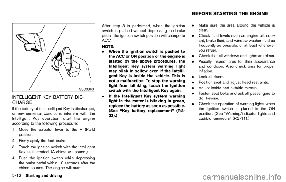
If the battery of the Intelligent Key is discharged,
or environmental conditions interfere with the
Intelligent Key operation, start the engine
according to the following procedure:
1. Move the selector lever to the P (Park)position.
2. Firmly apply the foot brake.
3. Touch the ignition switch with the Intelligent Key as illustrated. (A chime will sound.)
4. Push the ignition switch while depressing the brake pedal within 10 seconds after the
chime sounds. The engine will start. After step 3 is performed, when the ignition
switch is pushed without depressing the brake
pedal, the ignition switch position will change to
ACC.
NOTE:
.
When the ignition switch is pushed to
the ACC or ON position or the engine is
started by the above procedures, the
Intelligent Key system warning light
may blink in yellow even if the Intelli-
gent Key is inside the vehicle. This is
not a malfunction. To stop the warning
light from blinking, touch the ignition
switch with the Intelligent Key again.
. If the Intelligent Key system warning
light in the meter is blinking in green,
replace the battery as soon as possible.
(See “Key battery replacement” (P.8-
23) .) .
Make sure the area around the vehicle is
clear.
. Check fluid levels such as engine oil, cool-
ant, brake fluid, and window washer fluid as
frequently as possible, or at least whenever
you refuel.
. Check that all windows and lights are clean.
. Visually inspect tires for their appearance
and condition. Also check tires for proper
inflation.
. Lock all doors.
. Position seat and adjust head restraints.
. Adjust inside and outside mirrors.
. Fasten seat belts and ask all passengers to
do likewise.
. Check the operation of warning lights when
the ignition switch is placed in the ON
position. (See “Warning/indicator lights and
audible reminders” (P.2-11) .)
BEFORE STARTING THE ENGINE
Page 222 of 331
5-18Starting and driving
SSD0864
Shift lock release
If the battery charge is low or discharged, the
selector lever may not be moved from the P
(Park) position even with the brake pedal
depressed and the selector lever button pushed.
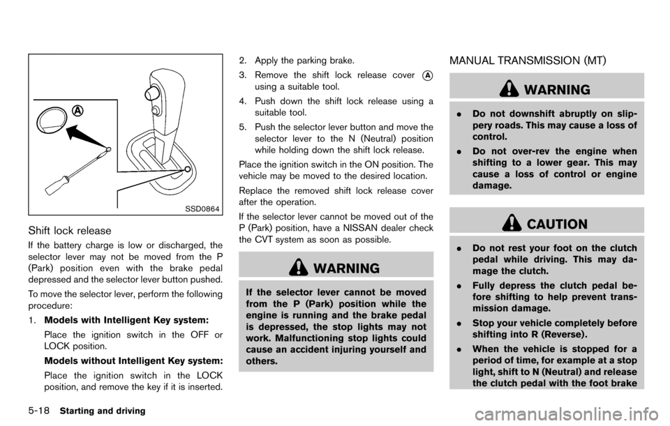
To move the selector lever, perform the following
procedure:
1.Models with Intelligent Key system:
Place the ignition switch in the OFF or
LOCK position.
Models without Intelligent Key system:
Place the ignition switch in the LOCK
position, and remove the key if it is inserted. 2. Apply the parking brake.
3. Remove the shift lock release cover
*A
using a suitable tool.
4. Push down the shift lock release using a suitable tool.
5. Push the selector lever button and move the selector lever to the N (Neutral) position
while holding down the shift lock release.
Place the ignition switch in the ON position. The
vehicle may be moved to the desired location.
Replace the removed shift lock release cover
after the operation.
If the selector lever cannot be moved out of the
P (Park) position, have a NISSAN dealer check
the CVT system as soon as possible.
WARNING
If the selector lever cannot be moved
from the P (Park) position while the
engine is running and the brake pedal
is depressed, the stop lights may not
work. Malfunctioning stop lights could
cause an accident injuring yourself and
others.
MANUAL TRANSMISSION (MT)
WARNING
. Do not downshift abruptly on slip-
pery roads. This may cause a loss of
control.
. Do not over-rev the engine when
shifting to a lower gear. This may
cause a loss of control or engine
damage.
CAUTION
.Do not rest your foot on the clutch
pedal while driving. This may da-
mage the clutch.
. Fully depress the clutch pedal be-
fore shifting to help prevent trans-
mission damage.
. Stop your vehicle completely before
shifting into R (Reverse) .
. When the vehicle is stopped for a
period of time, for example at a stop
light, shift to N (Neutral) and release
the clutch pedal with the foot brake
Page 233 of 331
mely deteriorated, the VDC system
may not operate properly and the
VDC warning light
may illumi-
nate.
. If engine control related parts are
not NISSAN recommended or are
extremely deteriorated, the VDC
warning light
may illuminate.
. When driving on extremely inclined
surfaces such as higher banked
corners, the VDC system may not
operate properly and the VDC warn-
ing light
may illuminate. Do not
drive on these types of roads.
. When driving on an unstable sur-
face such as a turntable, ferry,
elevator or ramp, the VDC warning
light
may illuminate. This is not
a malfunction. Restart the engine
after driving onto a stable surface.
. If wheels or tires other than the
NISSAN recommended ones are
used, the VDC system may not
operate properly and the VDC warn-
ing light
may illuminate. .
The VDC system is not a substitute
for winter tires or tire chains on a
snow covered road.
FREEING A FROZEN DOOR LOCK
To prevent a door lock from freezing, apply
deicer through the key hole. If the lock becomes
frozen, heat the key before inserting it into the
key hole or use the remote keyless entry keyfob.
ANTI-FREEZE
In the winter when it is anticipated that the
outside temperature will drop below 328F(0 8C) ,
check the anti-freeze to assure proper winter
protection. For additional information, see “En-
gine cooling system” (P.8-7) .
BATTERY
If the battery is not fully charged during
extremely cold weather conditions, the battery
fluid may freeze and damage the battery. To
maintain maximum efficiency, the battery should
be checked regularly. For additional information,
see “Battery” (P.8-13) .
DRAINING OF COOLANT WATER
If the vehicle is to be left outside without anti-
freeze, drain the cooling system, including the
engine block. Refill before operating the vehicle.
For details, see “Engine cooling system” (P.8-7) .
Starting and driving5-29
COLD WEATHER DRIVING
Page 263 of 331
8 Maintenance and do-it-yourself
Maintenance requirement ........................................................ 8-2Scheduled maintenance .................................................... 8-2
General maintenance ......................................................... 8-2
Where to go for service .................................................... 8-2
General maintenance ............................................................... 8-2 Explanation of maintenance items ................................... 8-2
Maintenance precautions ........................................................ 8-5
Engine compartment check locations .................................. 8-6 MR18DE engine .................................................................. 8-6
Engine cooling system ............................................................. 8-7
Checking engine coolant level ......................................... 8-8
Changing engine coolant .................................................. 8-8
Engine oil ........................................................................\
............ 8-9
Checking engine oil level .................................................. 8-9
Changing engine oil and filter .......................................... 8-9
Continuously Variable Transmission (CVT) fluid ............ 8-11
Brake and clutch fluid ........................................................... 8-12
Window washer fluid ............................................................ 8-12
Battery ........................................................................\
............... 8-13 Jump starting ..................................................................... 8-15
Variable voltage control system (if so equipped) .......... 8-15
Drive belt ........................................................................\
.......... 8-15
Spark plugs ........................................................................\
..... 8-16
Replacing spark plugs .................................................... 8-16 Air cleaner ........................................................................\
....... 8-17
Windshield wiper blades ..................................................... 8-18 Cleaning ........................................................................\
... 8-18
Replacing ........................................................................\
. 8-18
Rear window wiper blade ................................................... 8-19
Brakes ........................................................................\
.............. 8-19
Self-adjusting brakes .................................................... 8-19
Brake pad wear warning .............................................. 8-19
Fuses ........................................................................\
................ 8-20 Engine compartment ..................................................... 8-20
Passenger compartment .............................................. 8-22
Key battery replacement ...................................................... 8-23 Keyfob ........................................................................\
....... 8-24
Intelligent Key .................................................................. 8-25
Lights ........................................................................\
................ 8-26 Headlights ........................................................................\
8-27
Exterior and interior lights ............................................ 8-28
Wheels and tires ................................................................... 8-30 Tire pressure ................................................................... 8-30
Tire labeling ..................................................................... 8-33
Types of tires ................................................................... 8-35
Tire chains ....................................................................... 8-35
Changing wheels and tires .......................................... 8-36
Page 267 of 331
When performing any inspection or mainte-
nance work on your vehicle, always take care
to prevent serious accidental injury to yourself or
damage to the vehicle. The following are general
precautions which should be closely observed.
WARNING
.Park the vehicle on a level surface,
apply the parking brake securely
and block the wheels to prevent
the vehicle from moving. Move the
selector lever to the P (Park) posi-
tion or the shift lever to the N
(Neutral) position.
. Be sure the ignition switch is in the
OFF or LOCK position when per-
forming any parts replacement or
repairs.
. If you must work with the engine
running, keep your hands, clothing,
hair and tools away from moving
fans, belts and any other moving
parts.
. It is advisable to secure or remove
any loose clothing and remove any
jewelry, such as rings, watches, etc.
before working on your vehicle. .
Always wear eye protection when-
ever you work on your vehicle.
. If you must run the engine in an
enclosed space such as a garage, be
sure there is proper ventilation for
exhaust gases to escape.
. Never get under the vehicle while it
is supported only by a jack. If it is
necessary to work under the vehicle,
support it with safety stands.
. Keep smoking materials, flame and
sparks away from fuel tank and the
battery.
. The fuel filter or fuel lines should be
serviced by a NISSAN dealer be-
cause the fuel lines are under high
pressure even when the engine is
off.
CAUTION
.Do not work under the hood while
the engine is hot. Turn the engine
off and wait until it cools down.
. Avoid direct contact with used en-
gine oil and coolant. Improperly
disposed engine oil, and engine coolant and/or other vehicle fluids
can damage the environment. Al-
ways conform to local regulations
for disposal of vehicle fluid.
. Never leave the engine or the CVT
related component harnesses dis-
connected while the ignition switch
is in the ON position.
. Never connect or disconnect the
battery or any transistorized com-
ponent while the ignition switch is
in the ON position.
. Your vehicle is equipped with an
automatic engine cooling fan. It may
come on at any time without warn-
ing, even if the ignition key is in the
OFF position and the engine is not
running. To avoid injury, always
disconnect the negative battery
cable before working near the fan.
This “8. Maintenance and do-it-yourself” section
gives instructions regarding only those items
which are relatively easy for an owner to perform.
A genuine NISSAN Service Manual is also
available. (See “Owner’s Manual/Service Man-
ual order information” (P.9-20).)
You should be aware that incomplete or
Maintenance and do-it-yourself8-5
MAINTENANCE PRECAUTIONS
Page 285 of 331
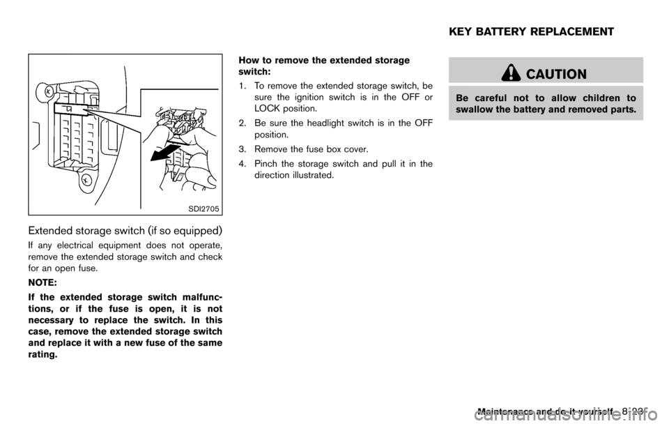
SDI2705
Extended storage switch (if so equipped)
If any electrical equipment does not operate,
remove the extended storage switch and check
for an open fuse.
NOTE:
If the extended storage switch malfunc-
tions, or if the fuse is open, it is not
necessary to replace the switch. In this
case, remove the extended storage switch
and replace it with a new fuse of the same
rating.How to remove the extended storage
switch:
1. To remove the extended storage switch, be sure the ignition switch is in the OFF or
LOCK position.
2. Be sure the headlight switch is in the OFF position.
3. Remove the fuse box cover.
4. Pinch the storage switch and pull it in the direction illustrated.
CAUTION
Be careful not to allow children to
swallow the battery and removed parts.
Maintenance and do-it-yourself8-23
KEY BATTERY REPLACEMENT
Page 286 of 331
8-24Maintenance and do-it-yourself
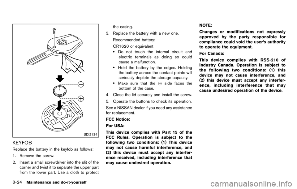
SDI2134
KEYFOB
Replace the battery in the keyfob as follows:
1. Remove the screw.
2. Insert a small screwdriver into the slit of thecorner and twist it to separate the upper part
from the lower part. Use a cloth to protect the casing.
3. Replace the battery with a new one.
Recommended battery:
CR1620 or equivalent
.Do not touch the internal circuit andelectric terminals as doing so could
cause a malfunction.
.Hold the battery by the edges. Holdingthe battery across the contact points will
seriously deplete the storage capacity.
.Make sure that the +side faces the
bottom of the case.
4. Close the lid securely and install the screw.
5. Operate the buttons to check its operation.
See a NISSAN dealer if you need any assistance
for replacement.
FCC Notice:
For USA:
This device complies with Part 15 of the
FCC Rules. Operation is subject to the
following two conditions: (1) This device
may not cause harmful interference, and
(2) this device must accept any interfer-
ence received, including interference that
may cause undesired operation. NOTE:
Changes or modifications not expressly
approved by the party responsible for
compliance could void the user’s authority
to operate the equipment.
For Canada:
This device complies with RSS-210 of
Industry Canada. Operation is subject to
the following two conditions: (1) this
device may not cause interference, and
(2) this device must accept any interfer-
ence, including interference that may
cause undesired operation of the device.