Page 160 of 489

When the doors are locked using one of the
following methods, the doors can not be opened
using the inside or outside door handles. The
doors must be unlocked to open the doors.
WARNING
●Always have the doors locked while
driving. Along with the use of seat belts,
this provides greater safety in the event
of an accident by helping to prevent
persons from being thrown from the
vehicle. This also helps keep children
and others from unintentionally open-
ing the doors, and will help keep out
intruders.
● Before opening any door, always look
for and avoid oncoming traffic.
● Do not leave children unattended inside
the vehicle. They could unknowingly ac-
tivate switches or controls. Unattended
children could become involved in seri-
ous accidents.
LOCKING WITH KEY
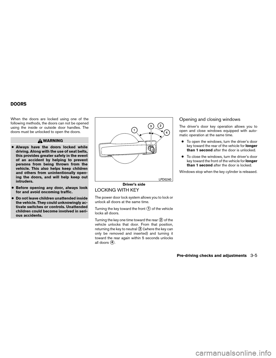
The power door lock system allows you to lock or
unlock all doors at the same time.
Turning the key toward the front
�1of the vehicle
locks all doors.
Turning the key one time toward the rear
�2of the
vehicle unlocks that door. From that position,
returning the key to neutral
�3(where the key can
only be removed and inserted) and turning it
toward the rear again within 5 seconds unlocks
all doors
�4.
Opening and closing windows
The driver’s door key operation allows you to
open and close windows equipped with auto-
matic operation at the same time.
● To open the windows, turn the driver’s door
key toward the rear of the vehicle for longer
than 1 second after the door is unlocked.
● To close the windows, turn the driver’s door
key toward the front of the vehicle for longer
than 1 second after the door is locked.
Windows stop when the key cylinder is released.
Driver’s side
LPD0240
DOORS
Pre-driving checks and adjustments3-5
Page 349 of 489

To remove the key from the ignition switch:1. Shift the shift selector to the P (Park) posi- tion with the ignition switch in the ON posi-
tion.
2. Place the ignition switch in the LOCK posi- tion.
3. Remove the key from the ignition switch.
If the shift selector is shifted to the P (Park)
position after the ignition switch is placed in the
OFF position or when the ignition switch cannot
be placed in the LOCK position, proceed as
follows to remove the key. 1. Move the shift selector into the P (Park) position.
2. Place the ignition switch slightly toward the ON position.
3. Place the ignition switch in the LOCK posi- tion.
4. Remove the key.
The shift selector is designed so it cannot move
out of P (Park) and into any of the other gear
positions if the ignition switch is placed in the
OFF position or if the key is removed from the
switch. The shift selector can be moved if the igni-
tion switch is in the ON position and the
foot brake pedal is depressed.
There is an OFF position between the
LOCK and ON positions. The OFF position
is indicated by a “1” on the ignition switch.
For models without NISSAN vehicle immo-
bilizer system: when the ignition switch is
in the OFF position, the steering wheel is
not locked.
In order for the steering wheel to be locked, it
must be turned about 1/8 of a turn clockwise
from the straight up position.
To lock the steering wheel, turn the ignition
to the LOCK position. Remove the key. To
unlock the steering wheel, insert the key
and turn it gently while rotating the steer-
ing wheel slightly right and left.
If the key will not turn from the LOCK posi-
tion, turn the steering wheel to the left or
right while turning the key to unlock the
key cylinder.KEY POSITIONS
LOCK: Normal parking position (0)
OFF: (Not used) (1)
ACC: (Accessories) (2)
This position activates electrical accessories
such as the radio when the engine is not running.
ON: Normal operating position (3)
This position turns on the ignition system and the
electrical accessories.
START: (4)
This position starts the engine. As soon as the
engine has started, release the key. It automati-
cally returns to the ON position.
5-12Starting and driving
Page 452 of 489
ENGINE
ModelVK56DE
Type Gasoline, 4-cycle, DOHC
Cylinder arrangement 8-cylinder, V-block, Slanted at 90°
Bore x Stroke in (mm) 3.858 x 3.622 (98 x 92)
Displacement cu in (cm
3) 338.78 (5,552)
Firing order 1–8–7–3–6–5–4–2
Idle speed
No adjustment is necessary.
A/T (in “N” position)
Ignition timing (degree B.T.D.C. at idle
speed)
CO % at idle
Spark plug
Standard Model
FFV Model
DILFR5A-11 DILFR5A-11D
Spark plug gap (Nominal) in (mm) 0.043 (1.1)
Camshaft operation Timing chain
This spark ignition system complies with the Canadian standard ICES-002.
SPECIFICATIONS
Technical and consumer information9-9