Page 390 of 454
Proper brake inspection intervals should
be followed.For more information regarding
brake inspections, see the appropriate mainte-
nance schedule information in the “NISSAN Ser-
vice and Maintenance Guide”.
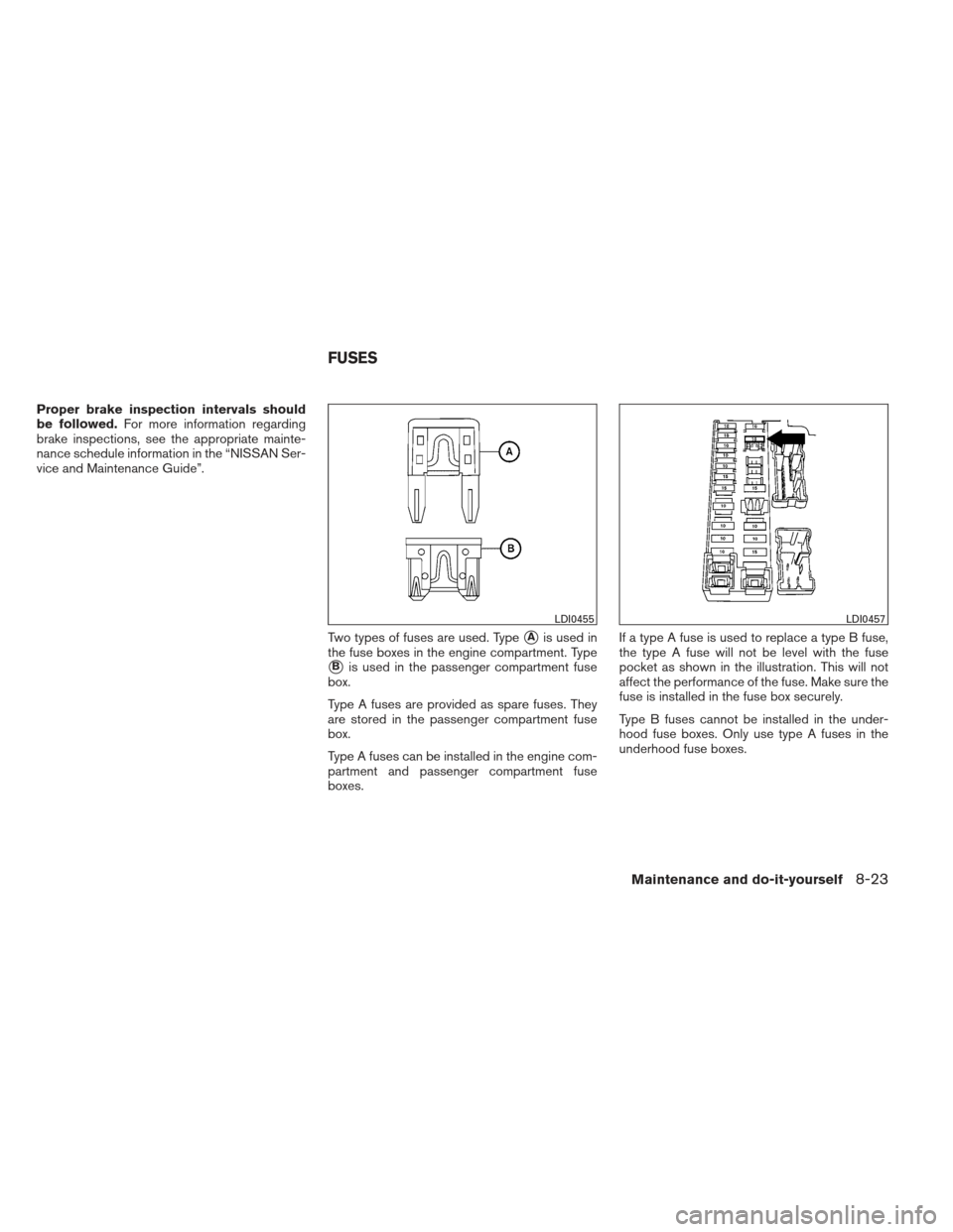
Two types of fuses are used. Type
�Ais used in
the fuse boxes in the engine compartment. Type
�Bis used in the passenger compartment fuse
box.
Type A fuses are provided as spare fuses. They
are stored in the passenger compartment fuse
box.
Type A fuses can be installed in the engine com-
partment and passenger compartment fuse
boxes. If a type A fuse is used to replace a type B fuse,
the type A fuse will not be level with the fuse
pocket as shown in the illustration. This will not
affect the performance of the fuse. Make sure the
fuse is installed in the fuse box securely.
Type B fuses cannot be installed in the under-
hood fuse boxes. Only use type A fuses in the
underhood fuse boxes.
LDI0455LDI0457
FUSES
Maintenance and do-it-yourself8-23
Page 391 of 454
ENGINE COMPARTMENT
CAUTION
Never use a fuse of a higher or lower
amperage rating than specified on the
fuse box cover. This could damage the
electrical system or cause a fire.
If any electrical equipment does not come on,
check for an open fuse. 1. Be sure the ignition switch and the headlight switch are OFF.
2. Open the engine hood. 3. Remove the fuse box cover by pushing the
tab and lifting the cover up.
4. Remove the fuse with the fuse puller. The fuse puller is located in the center of the fuse
block in the passenger compartment.
5. If the fuse is open
�A, replace it with a new
fuse
�B.
6. If a new fuse also opens, have the electrical system checked and repaired by a NISSAN
dealer.
Fusible links
If the electrical equipment does not operate and
fuses are in good condition, check the fusible
links. If any of these fusible links are melted,
replace with only Genuine NISSAN parts.
LDI0560WDI0452
8-24Maintenance and do-it-yourself
Page 392 of 454
PASSENGER COMPARTMENT
CAUTION
Never use a fuse of a higher or lower
amperage rating than specified on the
fuse box cover. This could damage the
electrical system or cause a fire.
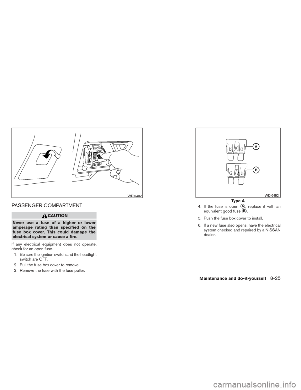
If any electrical equipment does not operate,
check for an open fuse. 1. Be sure the ignition switch and the headlight switch are OFF.
2. Pull the fuse box cover to remove.
3. Remove the fuse with the fuse puller. 4. If the fuse is open
�A, replace it with an
equivalent good fuse
�B.
5. Push the fuse box cover to install.
6. If a new fuse also opens, have the electrical system checked and repaired by a NISSAN
dealer.
WDI0402
Type A
WDI0452
Maintenance and do-it-yourself8-25
Page 394 of 454
CAUTION
Be careful not to allow children to swallow
the battery or removed parts.
NISSAN INTELLIGENT KEY™
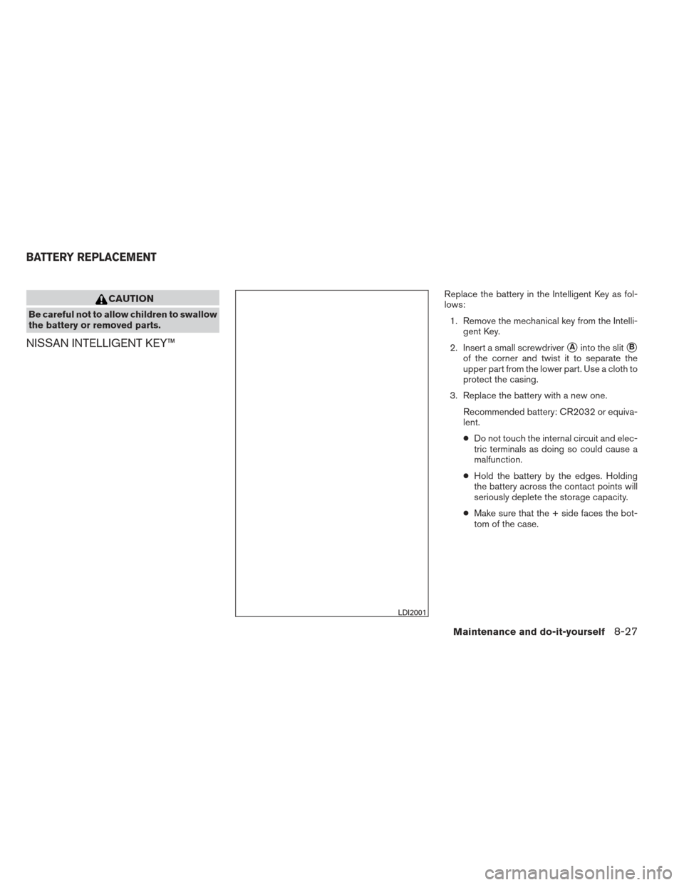
Replace the battery in the Intelligent Key as fol-
lows:1. Remove the mechanical key from the Intelli- gent Key.
2. Insert a small screwdriver
�Ainto the slit�B
of the corner and twist it to separate the
upper part from the lower part. Use a cloth to
protect the casing.
3. Replace the battery with a new one. Recommended battery: CR2032 or equiva-
lent.
●Do not touch the internal circuit and elec-
tric terminals as doing so could cause a
malfunction.
● Hold the battery by the edges. Holding
the battery across the contact points will
seriously deplete the storage capacity.
● Make sure that the + side faces the bot-
tom of the case.
LDI2001
BATTERY REPLACEMENT
Maintenance and do-it-yourself8-27
Page 395 of 454
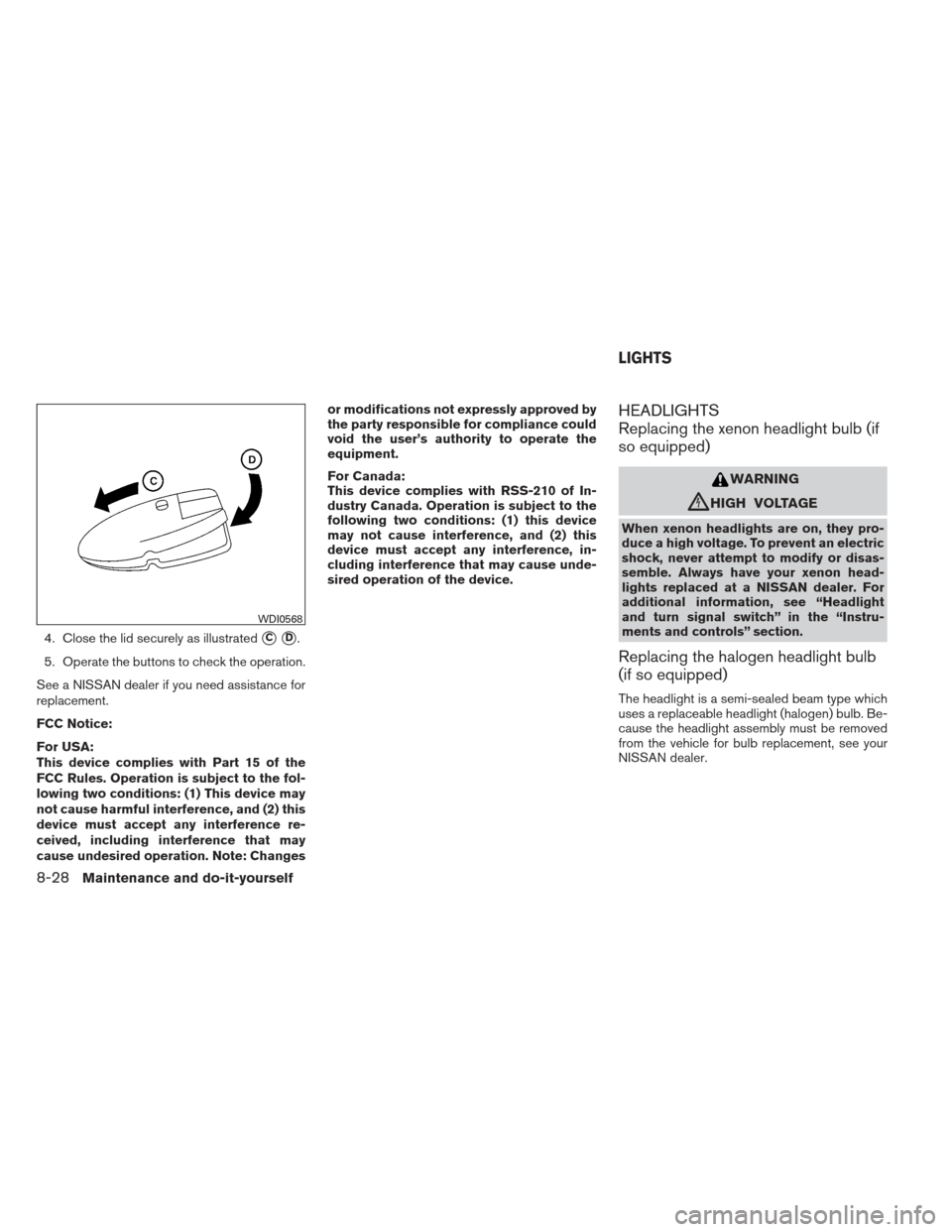
4. Close the lid securely as illustrated�C�D.
5. Operate the buttons to check the operation.
See a NISSAN dealer if you need assistance for
replacement.
FCC Notice:
For USA:
This device complies with Part 15 of the
FCC Rules. Operation is subject to the fol-
lowing two conditions: (1) This device may
not cause harmful interference, and (2) this
device must accept any interference re-
ceived, including interference that may
cause undesired operation. Note: Changes or modifications not expressly approved by
the party responsible for compliance could
void the user’s authority to operate the
equipment.
For Canada:
This device complies with RSS-210 of In-
dustry Canada. Operation is subject to the
following two conditions: (1) this device
may not cause interference, and (2) this
device must accept any interference, in-
cluding interference that may cause unde-
sired operation of the device.
HEADLIGHTS
Replacing the xenon headlight bulb (if
so equipped)
WARNING
cHIGH VOLTAGE
When xenon headlights are on, they pro-
duce a high voltage. To prevent an electric
shock, never attempt to modify or disas-
semble. Always have your xenon head-
lights replaced at a NISSAN dealer. For
additional information, see “Headlight
and turn signal switch” in the “Instru-
ments and controls” section.
Replacing the halogen headlight bulb
(if so equipped)
The headlight is a semi-sealed beam type which
uses a replaceable headlight (halogen) bulb. Be-
cause the headlight assembly must be removed
from the vehicle for bulb replacement, see your
NISSAN dealer.
WDI0568
LIGHTS
8-28Maintenance and do-it-yourself
Page 397 of 454
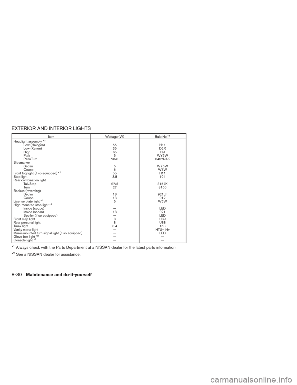
EXTERIOR AND INTERIOR LIGHTS
ItemWattage (W)Bulb No.*1
Headlight assembly *2Low (Halogen) 55H11
Low (Xenon) 35D2R
High 65H9
Park 5WY5W
Park/Turn 28/83457NAK
Sidemarker Sedan 5WY5W
Coupe 5W5W
Front fog light (if so equipped) *
255 H11
Step light 3.8194
Rear combination light Tail/Stop 27/83157K
Turn 273156
Backup (reversing) Sedan 18921LF
Coupe 13912
License plate light *
25 W5W
High-mounted stop light *2Inside (coupe) —LED
Inside (sedan) 18921
Spoiler (if so equipped) —LED
Front map light 8U89
Rear personal light 8U88
Trunk light 3.4158
Vanity mirror light —HTU–14v
Mirror-mounted turn signal light (if so equipped) —LED
Glove box light *
2——
Console light *2——
*1Always check with the Parts Department at a NISSAN dealer for the latest parts information.
*
2See a NISSAN dealer for assistance.
8-30Maintenance and do-it-yourself
Page 403 of 454
CAUTION
Never force the covers into place because
the hinge pins can be damaged. Follow
the removal and installation instructions
to prevent inoperability of the covers.
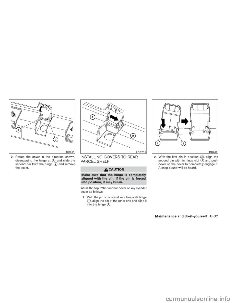
REMOVING COVERS FROM REAR
PARCEL SHELF
Remove the top tether anchor cover or key cylin-
der cover as follows:1. Lift the cover to the full open position.
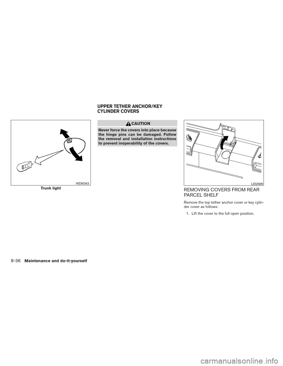
Trunk light
WDI0343LDI2009
UPPER TETHER ANCHOR/KEY
CYLINDER COVERS
8-36Maintenance and do-it-yourself
Page 404 of 454
2. Rotate the cover in the direction shown,disengaging the hinge at
�1and slide the
second pin from the hinge
�2and remove
the cover.
INSTALLING COVERS TO REAR
PARCEL SHELF
CAUTION
Make sure that the hinge is completely
aligned with the pin. If the pin is forced
into position, it may break.
Install the top tether anchor cover or key cylinder
cover as follows: 1. With the pin on one end kept free of its hinge
�1, align the pin of the other end and slide it
into the hinge
�2. 2. With the first pin in position
�2, align the
second pin with its hinge slot
�1and push
down on the cover to completely engage it.
A snap sound will be heard.
LDI2010LDI2011LDI2012
Maintenance and do-it-yourself8-37