Page 16 of 454
20. Vehicle information display controls(P. 2-17)
21. Hood release (P. 3-24)
22. Trunk opener (P. 3-24) Vehicle Dynamic Control (VDC) OFF
switch (P. 2-36)
NISSAN Intelligent Key™ port (P. 5-7)
*: Refer to the separate Navigation System Own-
er’s Manual (if so equipped) .
See the page number indicated in paren-
theses for operating details.
Illustrated table of contents0-9
Page 74 of 454

The pretensioner is encased with the seat belt
retractor. These seat belts are used the same way
as conventional seat belts.
When a pretensioner activates, smoke is re-
leased and a loud noise may be heard. This
smoke is not harmful and does not indicate a fire.
Care should be taken not to inhale it, as it may
cause irritation and choking. Those with a history
of a breathing condition should get fresh air
promptly.
After pretensioner activation, load limiters allow
the seat belt to release webbing (if necessary) to
reduce forces against the chest.
The supplemental air bag warning light
is
used to indicate malfunctions in the pretensioner
system. (See �SUPPLEMENTAL AIR BAG
WARNING LIGHT� in this section for more de-
tails.) If the operation of the supplemental air bag
warning light indicates there is a malfunction,
have the system checked by a NISSAN dealer.
When selling your vehicle, we request that you
inform the buyer about the pretensioner system
and guide the buyer to the appropriate sections
in this Owner’s Manual.1. SRS Air Bag Warning Labels (located
on the sun visors)
SUPPLEMENTAL AIR BAG
WARNING LABELS
Warning labels about the supplemental front-
impact air bag system are placed in the vehicle as
shown in the illustration.
SUPPLEMENTAL AIR BAG
WARNING LIGHT
The supplemental air bag warning light,
displaying
in the instrument panel, moni-
tors the circuits for the air bag systems, preten-
sioners and all related wiring.
When the ignition is placed in the ON or START
position, the supplemental air bag warning light
illuminates for about 7 seconds and then turns
off. This means the system is operational.
WRS0895LRS0100
Safety—Seats, seat belts and supplemental restraint system1-55
Page 77 of 454

2 Instruments and controls
Instrument panel...................................2-2
Meters and gauges ................................2-3
Speedometer and odometer . . ...................2-4
Tachometer ....................................2-5
Engine coolant temperature gauge ...............2-5
Fuel gauge ....................................2-6
Compass display (if so equipped) ...................2-6
Compass display ...............................2-7
Warning/indicator lights and audible reminders ......2-10
Checking bulbs ............................... 2-10
Warning lights ................................ 2-11
Indicator lights ................................ 2-14
Audible reminders ............................. 2-16
Vehicle information display ......................... 2-17
How to use the Vehicle Information Display .......2-17
Security systems ................................. 2-25
Vehicle security system ......................... 2-25
NISSAN vehicle immobilizer system .............2-27
Windshield wiper and washer switch ...............2-27
Switch operation .............................. 2-27
Rear window and outside mirror (if so equipped)
defroster switch .................................. 2-28
Headlight and turn signal switch. . ..................2-29Xenon headlights (if so equipped)
...............2-29
Headlight control switch ........................ 2-30
Daytime running light system (Canada only) ......2-32
Instrument brightness control ...................2-33
Turn signal switch ............................. 2-33
Fog light switch (if so equipped) ................2-34
Hazard warning flasher switch .....................2-34
Horn ............................................ 2-35
Heated seat (if so equipped) .......................2-35
Vehicle Dynamic Control (VDC) off switch ...........2-36
Power outlet ..................................... 2-36
Storage ......................................... 2-37
Map pockets .................................. 2-37
Seatback pockets (if so equipped) ..............2-38
Storage pouch (if so equipped) .................2-38
Sunglasses
holder............................. 2-38
Cup holders . . . ............................... 2-39
Glove box .................................... 2-41
Console box .................................. 2-41
Storage box (if so equipped) ....................2-42
Covered storage box ........................... 2-42
Grocery hooks ................................ 2-42
Cargo net (if so equipped) ......................2-43
Page 80 of 454
20. Vehicle information display controls(P. 2-17)
21. Hood release (P. 3-24)
22. Trunk opener (P. 3-24) Vehicle Dynamic Control (VDC) OFF
switch (P. 2-36)
NISSAN Intelligent Key™ port (P. 5-7)
*: Refer to the separate Navigation System Own-
er’s Manual (if so equipped) .
See the page number indicated in paren-
theses for operating details.
1. Tachometer
2. Speedometer
3. Fuel gauge
4. Engine coolant temperature gauge
5. Odometer/twin trip odometer
6. Twin trip odometer change button 7. Vehicle information display
8. Instrument brightness control
WIC1259
METERS AND GAUGES
Instruments and controls2-3
Page 81 of 454
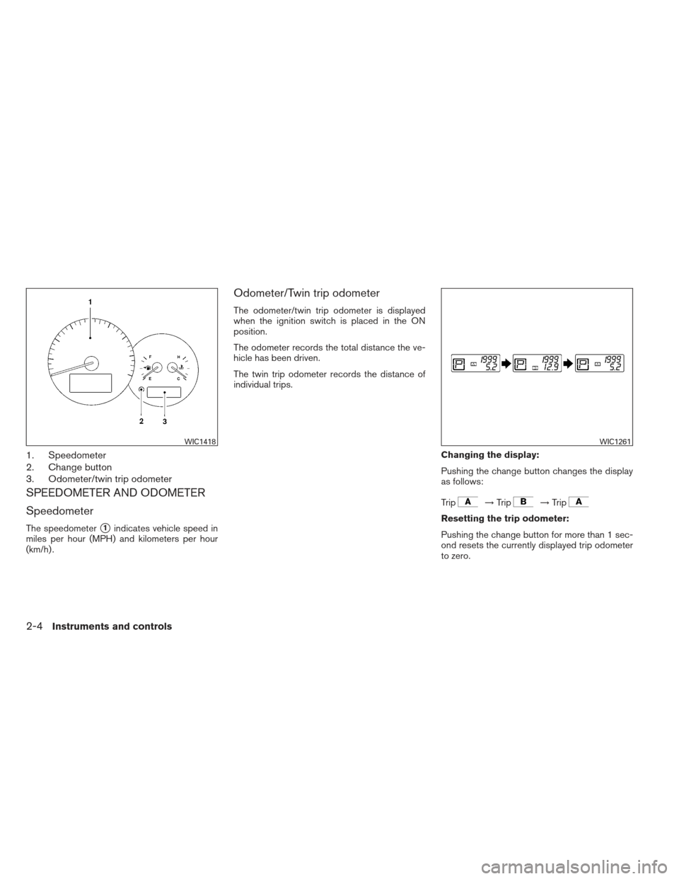
1. Speedometer
2. Change button
3. Odometer/twin trip odometer
SPEEDOMETER AND ODOMETER
Speedometer
The speedometer�1indicates vehicle speed in
miles per hour (MPH) and kilometers per hour
(km/h) .
Odometer/Twin trip odometer
The odometer/twin trip odometer is displayed
when the ignition switch is placed in the ON
position.
The odometer records the total distance the ve-
hicle has been driven.
The twin trip odometer records the distance of
individual trips.
Changing the display:
Pushing the change button changes the display
as follows:
Trip
→Trip→Trip
Resetting the trip odometer:
Pushing the change button for more than 1 sec-
ond resets the currently displayed trip odometer
to zero.
WIC1418WIC1261
2-4Instruments and controls
Page 83 of 454
")
FUEL GAUGE
The gauge indicates theapproximatefuel level
in the tank.
The gauge may move slightly during braking,
turning, acceleration, or going up or down hills.
The gauge needle returns to E (Empty) after the
ignition switch is placed in the OFF position.
The low fuel warning light comes on when the
amount of fuel in the tank is getting low.
Refill the fuel tank before the gauge regis-
ters E (Empty) . The
indicates that the fuel-filler door is
located on the driver’s side of the vehicle.
CAUTION
● If the vehicle runs out of fuel,
the
Malfunction Indicator Light
(MIL) may come on. Refuel as soon as
possible. After a few driving trips,
the
light should turn off. If the
light remains on after a few driving
trips, have the vehicle inspected by a
NISSAN dealer.
● For additional information, see “Mal-
function Indicator Light (MIL)” later in
this section. This unit measures terrestrial magnetism and in-
dicates the direction of the vehicle’s heading.
With the ignition switch placed in the ON posi-
tion, press the
button as described in the
chart below to activate various features of the
automatic anti-glare rearview mirror.
Push and hold
the
button for about: Feature:
(Push button again for about 1 sec-
ond to change settings)
1 second Compass display toggles on/off
5 seconds Compass zone can be changed to
correct false compass readings
9 seconds Compass enters calibration mode
For information about the automatic anti-glare
feature, refer to “Automatic anti-glare rearview
mirror” in the “Pre-driving checks and adjust-
ments” section.LIC1060
COMPASS DISPLAY (if so equipped)
2-6Instruments and controls
Page 84 of 454

Press thebutton for about 1 second when
the ignition switch is placed in the ON position to
toggle the compass display
�1on or off. The
display will indicate the direction of the vehicle’s
heading.
N: North
E: East
S: South
W: West
If the display reads “C”, calibrate the compass by
driving the vehicle in three complete circles at
less than 5 MPH (8 km/h) . You can also calibrate the compass by driving
your vehicle on your everyday route. The com-
pass will be calibrated once it has tracked three
complete circles.
COMPASS DISPLAY
Press thebutton when the ignition switch
is placed in the ON position. The direction will be
displayed.
Zone variation change procedure
The difference between magnetic north and geo-
graphical north is known as variance. In some
areas, this difference can sometimes be great
enough to cause false compass readings. Follow
these instructions to set the variance for your
particular location if this happens:
1. Establish your location on the zone map. Refer to the illustration. Record your zone
number.
2. Place the ignition switch in the ON position.
3. Press the
button in for 5 seconds until
the current zone entry number is displayed.
4. Press the
button repeatedly until the
desired zone entry number is displayed. Once the desired zone number is displayed, stop
pressing the
button and the display will
show compass direction within a few seconds.
NOTE:
Use zone number 5 for Hawaii.
LIC1487
Instruments and controls2-7
Page 85 of 454
●If a magnet is located near the com-
pass or the vehicle is driven where the
terrestrial magnetism is disturbed, the
compass display may not indicate the
correct direction.
● In places where the terrestrial magne-
tism is disturbed, the correction of the
direction starts automatically.
Inaccurate compass direction:
The compass display is equipped with automatic
correction function. If the correct direction is not
shown, follow this procedure. 1. With the display turned on, press and hold the
switch for about 9 seconds. The
display will read “C.”
2. Calibrate the compass by driving the vehicle in three complete circles at a maximum
speed of 5 MPH (8 km/h) .
3. After completing the circles the display should return to normal.
● If the compass deviates from the correct
indication soon after repeated adjustment,
have the compass checked at an authorized
NISSAN dealer.
WIC0355
2-8Instruments and controls

21. Hood release (P. 3-24)
22. Trunk opener (P. 3-24) Vehicle Dynamic Control (VDC) OFF
switch (P. 2-36)
NISSAN Intelligent Key™ port (P. 5-7)
*: Re")

21. Hood release (P. 3-24)
22. Trunk opener (P. 3-24) Vehicle Dynamic Control (VDC) OFF
switch (P. 2-36)
NISSAN Intelligent Key™ port (P. 5-7)
*: Re")