Page 664 of 714
Vehicle care and maintenance
7-63
7
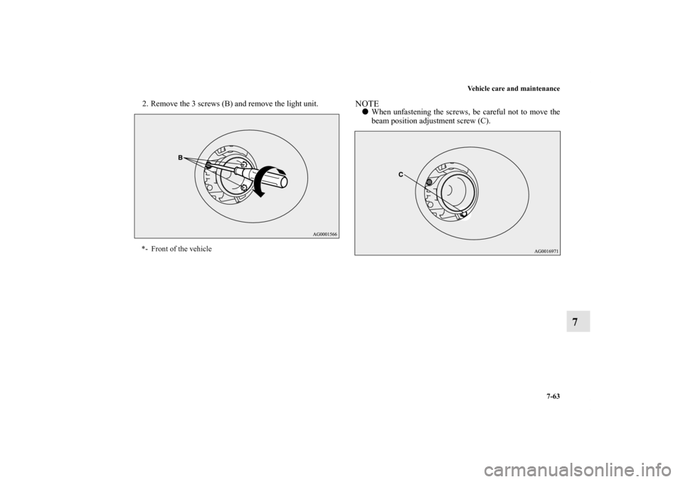
2. Remove the 3 screws (B) and remove the light unit.
NOTE�When unfastening the screws, be careful not to move the
beam position adjustment screw (C).
*- Front of the vehicle
BK0138000US.book 63 ページ 2011年4月13日 水曜日 午前11時17分
Page 666 of 714
Vehicle care and maintenance
7-65
7
5. To install the bulb, perform the removal steps in reverse.
Rear combination lights
N00943700432
1. Remove the screws (A) that hold the light unit and remove
the light unit.
CAUTION
!�Handle halogen light bulb with care. The gas inside
a halogen light bulb is highly pressurized, so drop-
ping, knocking, or scratching a halogen light bulb
can cause it to shatter.�Never hold the halogen light bulb with a bare hand,
dirty glove, etc. The oil from your hand could cause
the bulb to break the next time the fog lights are
used.
If the glass surface is dirty, clean it with alcohol and
let it dry completely before installing the bulb.
BK0138000US.book 65 ページ 2011年4月13日 水曜日 午前11時17分
Page 667 of 714
7-66 Vehicle care and maintenance
7
2. Turn the socket and bulb assembly counterclockwise to
remove it.NOTE�The tail and stop light uses an LED instead of the bulb.
Check with an authorized Mitsubishi Motors dealer or a
repair facility of your choice when the light needs to be
repaired or replaced.3. Pull the bulb out of the socket.B- Tail and stop light (LED) - cannot be replaced
C- Rear turn-signal light
BK0138000US.book 66 ページ 2011年4月13日 水曜日 午前11時17分
Page 668 of 714
Vehicle care and maintenance
7-67
7
4. To install the bulb, perform the removal steps in reverse.NOTE�When mounting the light unit, align the clips (D) on the
light unit with the hole in the body.
Back-up lights
N00929100041
1. Open the tailgate.
2. Insert a screwdriver into the notch of the cover and pry
gently to remove the cover.NOTE�Wrap a cloth around the tip of the screwdriver to keep
from scratching the cover.
BK0138000US.book 67 ページ 2011年4月13日 水曜日 午前11時17分
Page 670 of 714
Vehicle care and maintenance
7-69
7
Rear side-marker lights
N00935400094
1. Open the lower gate and pull back the cover between the
passenger compartment and the lower gate.
2. Remove the cover after you remove each of the 4 clips (A)
by inserting a screw driver into the clip groove and lever-
ing it toward the vehicle body.3. Remove the light mounting screw (B) and remove the
light unit.
BK0138000US.book 69 ページ 2011年4月13日 水曜日 午前11時17分
Page 671 of 714
7-70 Vehicle care and maintenance
7
4. Remove the socket and bulb assembly (C) together by
turning it counterclockwise, and then remove the bulb by
pulling it out.
5. To install the bulb, perform the removal steps in reverse.
NOTE�When mounting the light unit, align the pins (D) on the
light unit with the hole in the body.
BK0138000US.book 70 ページ 2011年4月13日 水曜日 午前11時17分
Page 672 of 714
Vehicle care and maintenance
7-71
7
License plate lights
N00944000360
1. When removing the light unit (A), push it toward the left
side of the vehicle body.2. Use a screw driver to gently pry up the tab (B) and remove
the lens.
NOTE�Wrap a cloth around the tip of the screwdriver to keep
from scratching the lens.
BK0138000US.book 71 ページ 2011年4月13日 水曜日 午前11時17分
Page 673 of 714
7-72 Vehicle care and maintenance
7
3. Pull the bulb out of the socket. 4. To install the bulb, perform the removal steps in reverse.
NOTE�When mounting the light unit, insert tab (C) first then
align tab (D) with its hole.
BK0138000US.book 72 ページ 2011年4月13日 水曜日 午前11時17分
 that hold the light unit and remove
the")


 together by
turning it counterclockwise, and then remove the bulb by
pulling it out.
5. To install the bulb, perform the")
, push it toward the left
side of the vehicle body.2. Use a screw driver to gently pry up the t")
