Page 339 of 722

3-244 Features and controls
3
NOTE�A light in the instrument panel flashes to show when the
front and rear turn signal lights are working properly.
If this light flashes faster than usual, check for a burned
out light bulb or malfunctioning connection.
If the panel light does not come on when the lever is
moved, check for a blown fuse or a burned out bulb in the
panel.
Have the vehicle inspected by an authorized Mitsubishi
Motors dealer or a repair facility of your choice.
�The turn signal light 3-flash function for lane changes can
be deactivated.
See your authorized Mitsubishi Motors dealer for details.
For vehicles equipped with the Mitsubishi Multi-Commu-
nication System, adjustments can be made using screen
operations. For further details, refer to the separate
owner’s manual.
�You can adjust the time required to operate the lever for
the 3-flash function.
See your authorized Mitsubishi Motors dealer for details.
Hazard warning flasher switch
N00522700217
If you press the flasher switch, the front and rear turn signals
will flash intermittently, and so will the hazard warning lights.
This is an emergency warning system and should not be used
when the vehicle is in motion, except for emergencies.
If you need to leave your vehicle, the flashers will keep work-
ing after the ignition key is removed. NOTE�If you keep the flashers on for several hours with the
engine turned off, the battery will run down.
BK0138600US.book 244 ページ 2011年7月17日 日曜日 午後2時32分
Page 574 of 722

For emergencies
6-3
6
3. You could be injured if the vehicles move. Set the parking
brake firmly on each vehicle. Put an automatic transaxle,
CVT or Twin Clutch SST in “P” (PARK) or a manual
transaxle in “N” (Neutral). Turn the ignition key to the
“LOCK” position. NOTE�Turn off all lights, heater, and other electrical loads. This
will avoid sparks and help save both batteries.
4. Make sure your battery electrolyte is at the proper level.
(Refer to “Checking battery electrolyte level” on page 7-
26.)5. For vehicles equipped with turbocharger, remove the air
duct and then the battery upper cover.
(Refer to “Removing and installing the battery upper
cover” on page 7-23.)
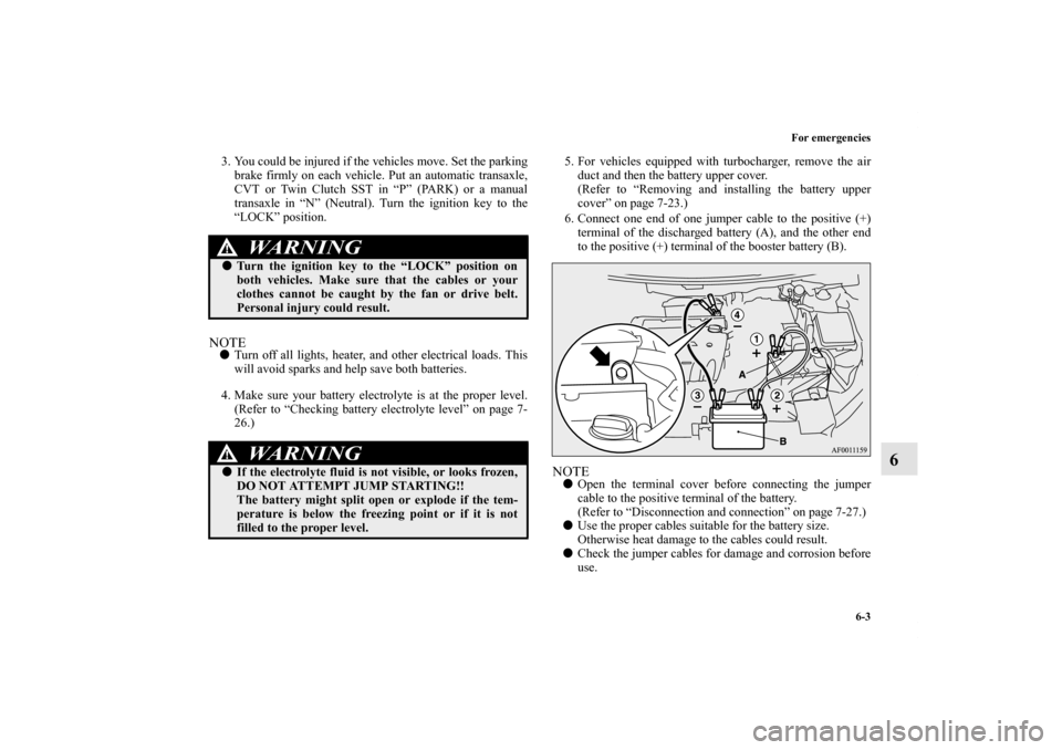
6. Connect one end of one jumper cable to the positive (+)
terminal of the discharged battery (A), and the other end
to the positive (+) terminal of the booster battery (B).
NOTE�Open the terminal cover before connecting the jumper
cable to the positive terminal of the battery.
(Refer to “Disconnection and connection” on page 7-27.)
�Use the proper cables suitable for the battery size.
Otherwise heat damage to the cables could result.
�Check the jumper cables for damage and corrosion before
use.
WA R N I N G
!�Turn the ignition key to the “LOCK” position on
both vehicles. Make sure that the cables or your
clothes cannot be caught by the fan or drive belt.
Personal injury could result.
WA R N I N G
!�If the electrolyte fluid is not visible, or looks frozen,
DO NOT ATTEMPT JUMP STARTING!!
The battery might split open or explode if the tem-
perature is below the freezing point or if it is not
filled to the proper level.
BK0138600US.book 3 ページ 2011年7月17日 日曜日 午後2時32分
Page 620 of 722
Vehicle care and maintenance
7-23
7 Battery
N00939100783
The condition of the battery is very important for quick starting
and to keep the vehicle’s electrical system working properly.
Check the battery regularly. Removing and installing the battery upper cover
(vehicles with turbocharger)
N00901300012
To r e m o v e1. Remove the clips (A), and then remove the air duct (B).
WA R N I N G
!�An SRS airbag sensor is located in the front of the
engine compartment near the battery.
When checking or replacing the battery, or when
working around this area, do not strike or damage
this sensor.
WA R N I N G
!�Turn the ignition key to the “LOCK” position on
vehicle. Make sure that your clothes cannot be
caught by the fan or drive belt. Personal injury
could result.
BK0138600US.book 23 ページ 2011年7月17日 日曜日 午後2時32分