Page 154 of 494
Features and controls
3-59
3
To adjust the mirror positionThe outside rearview mirrors can be adjusted when the ignition
key is in the “ON” or “ACC” position.
Move the lever (A) to the same side as the mirror you wish to
adjust.
Press the switch (B) to adjust the mirror position. NOTE�After adjusting, return the lever to the “•” (off) position.
To fold the mirrorThe outside mirror can be folded in toward the side window to
prevent damage when parking in tight locations.
L- Left outside mirror adjustment
R- Right outside mirror adjustment
1- Up
2- Down
3- Right
4- Left
BK0132701US.book 59 ページ 2010年12月6日 月曜日 午後2時3分
Page 155 of 494

N00549300146
When the rear window defogger switch is pressed, the outside
rearview mirrors are defogged or defrosted. Current will flow
thr")
3-60 Features and controls
3
Heated mirror
(if so equipped)
N00549300146
When the rear window defogger switch is pressed, the outside
rearview mirrors are defogged or defrosted. Current will flow
through the heater element inside the mirrors, thus clearing
away frost or condensation.
The indicator light (C) will illuminate while the defogger is on.
The heater will be turned off automatically in about 17 min-
utes.
Ignition switch
N00512400631
LOCKThe engine is off and the steering wheel is locked. The key can
be inserted and removed only when the switch is in this posi-
tion. ACCAllows operation of electrical accessories with the engine off. ON The engine runs and all accessories can be used.
CAUTION
!�Electric current will flow through the heating wires
on the rear window to help clear away moisture or
frost when the rear defogger switch is pressed.
When the top is completely lowered, keep the rear
window defogger turned off to avoid damage to the
top (ECLIPSE SPYDER only).
Manual transaxle Automatic transaxle
BK0132701US.book 60 ページ 2010年12月6日 月曜日 午後2時3分
Page 196 of 494
 Rules (For vehicl")
Features and controls
3-101
3
General information
N00533000207
Your tire pressure monitoring system operates on a radio fre-
quency subject to Federal Communications Commission
(FCC) Rules (For vehicles sold in U.S.A.) and Industry Canada
Rules (For vehicles sold in Canada). This device complies with
Part 15 of the FCC Rules and RSS- Gen of the Industry Canada
Rules.
Operation is subject to the following two conditions.
�This device may not cause harmful interference.
�This device must accept any interference received, includ-
ing interference that may cause undesired operation.
Rear-view camera
(if so equipped)
N00546200085
When the gearshift lever (for vehicles with manual transaxle)
or the selector lever (for vehicles with automatic transaxle) is
in the “R” position with the ignition key in the “ON” position,
the rear-view camera image will be displayed on the left por-
tion of the inside rearview mirror.
When the gearshift lever or the selector lever is shifted out of
the “R” position, the rear-view camera image will turn off.
CAUTION
!�Changes or modifications not expressly approved by
the manufacturer for compliance could void the
user’s authority to operate the equipment.
WA R N I N G
!�Never rely solely on the rear-view camera to clear
the area behind your vehicle. Always check visually
behind and all around your vehicle for persons, ani-
mals, obstructions or other vehicles. Failure to do so
can result in vehicle damage, serious injury or
death.�The rear-view camera is an aid system for backing
up, but it is not a substitute for your visual confir-
mation.�The view on the rear-view camera display is limited,
and objects outside the view, such as under the
bumper or around either corner of the bumper end,
cannot be seen on the display.
BK0132701US.book 101 ページ 2010年12月6日 月曜日 午後2時3分
Page 197 of 494
3-102 Features and controls
3
Location of rear-view cameraThe rear-view camera (A) is in the rear bumper.
Rear-view camera display
N00547700016
The rear-view camera image appears on the left portion of the
rear-view mirror.
CAUTION
!�If the camera lens gets dirty, a clear image cannot be
obtained. As necessary, rinse the lens with clean
water and gently wipe with a clean, soft cloth.�To avoid damaging the camera;
• Do not rub the cover excessively or polish it by
using an abrasive compound.
• Do not disassemble the camera.
• Do not splash hot water directly on the lens.
• Do not spray the camera and its surroundings with
high-pressure water.
CAUTION
!�The rear-view camera uses a wide-angle lens. As a
result, images and distances shown on the rear-view
camera display are not exact.
BK0132701US.book 102 ページ 2010年12月6日 月曜日 午後2時3分
Page 198 of 494
Features and controls
3-103
3
NOTE�Mirror image is displayed on the rear-view camera dis-
play.
�Monitor brightness is adjusted automatically by sensors.
�In the event the monitor is continuously used for more
than 5 minutes, the monitor will automatically turn off.
�Under certain circumstances, it may become difficult to
see an image on the display, even when the system is
functioning correctly.
• In a dark area, such as at night.
• When water drops or condensation are on the lens.
• When sun light or headlights shine directly into the lens.
→ When the camera picks up extremely bright light,
such as sunlight reflected off the rear bumper, a bright
vertical line may appear on the display.
BK0132701US.book 103 ページ 2010年12月6日 月曜日 午後2時3分
Page 231 of 494
3-136 Features and controls
3
NOTE�If your vehicle is equipped with heated mirrors, mist can
also be removed from the outside rearview mirrors when
the rear window defogger switch is pressed. (Refer to
“Heated mirror” on page 3-60.)
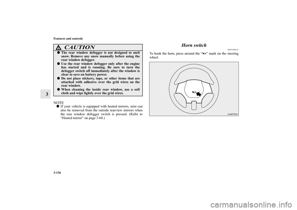
Horn switch
N00523800143
To honk the horn, press around the “ ” mark on the steering
wheel.
CAUTION
!�The rear window defogger is not designed to melt
snow. Remove any snow manually before using the
rear window defogger.�Use the rear window defogger only after the engine
has started and is running. Be sure to turn the
defogger switch off immediately after the window is
clear to save on battery power.�Do not place stickers, tape, or other items that are
attached with adhesive over the grid wires on the
rear window.�When cleaning the inside rear window, use a soft
cloth and wipe lightly over the grid wires.
BK0132701US.book 136 ページ 2010年12月6日 月曜日 午後2時3分
Page 432 of 494
Vehicle care and maintenance
7-41
7
Passenger compartment fuse location tablePassenger compartment fuse location
No.
Symbol
Electrical system
Capacity
1 Ignition coil 10 A
2 Gauge 7.5 A
3 Back-up lights 7.5 A
4 Electric convertible top 7.5 A
5 Relay 7.5 A
6 Door mirror heater 7.5 A
7— — —
8 Engine control 7.5 A
9— — —
10 — — —
11 Outside rearview mirrors 7.5 A
12 Engine control 7.5 A
13 — — —
14 Rear window wiper 15 A
15 Power door locks 15 A
16 Power outlet 15 A
17 — — —
18 — — —
19 Heater 30 A
20 Rear window defogger 30 A
BK0132701US.book 41 ページ 2010年12月6日 月曜日 午後2時3分
Page 442 of 494
Vehicle care and maintenance
7-51
7
ECLIPSE SPYDER
NOTE�The dome light/reading lights use LEDs rather than bulbs.
For repair and replacement, contact an authorized
Mitsubishi Motors dealer or a repair facility of your
choice.
Headlights (vehicles with high intensity discharge
headlights)
N00943100159
Do not attempt to disassemble or repair headlights, and do not
attempt to replace their bulbs.
Description
Wattage
1- Vanity mirror light 1.4 W
2-Dome light (Front)
/Reading lights (if so equipped)—
3-Reading lights on an inside rearview mir-
ror (if so equipped)4.3 W
4- Glove compartment light 1.4 W
WA R N I N G
!�A high voltage is present in the power circuit and in
the bulbs and bulb terminals. To avoid the risk of an
electric shock, contact an authorized Mitsubishi
Motors dealer whenever repair or replacement is
necessary.
BK0132701US.book 51 ページ 2010年12月6日 月曜日 午後2時3分
 to the same si")
 is in the rear bumper.
Rear-view camera display
N00547700016
The rear-view camera image appears on the left portion o")