2012 MERCEDES-BENZ SLK250 lock
[x] Cancel search: lockPage 291 of 334
Transporting the vehicle
The towing eye can be used to pull the vehicle
onto a trailer or transporter for transporting
purposes.
X Vehicles with manual transmission:
shift to neutral.
X Vehicles with automatic transmission:
turn the SmartKey to position 2in the
ignition lock.
X Move the selecto rlever to N.
As soon as the vehicle is loaded:
X Preven tthe vehicle from rolling away by
applying the parking brake.
X Vehicles with manual transmission:
shift to first gear or reverse gear.
X Vehicles with automatic transmission:
move the selector lever to P.
X Turn the SmartKey to position 0in the
ignition lock and remove the SmartKey
from the ignition lock.
X Secure the vehicle.
! Only lash the vehicle down by the wheels
or wheel rims, not by parts of the vehicle
such as axle or steering components.
Otherwise, the vehicle could be damaged. Tow-starting (emergency starting)
When tow-starting your vehicle, it is
important that you follow the safety
instructions (Y page 287).
! Vehicles with automatic transmission
must not be started by tow-starting. This
could otherwise damage the transmission.
For further information on "Jump-starting"
see (Y page 285).
Before tow-starting the following conditions
must be fulfilled:
R the battery is connected.
R the engine has cooled down.
R the catalytic converter has cooled down. X
Switch on the hazard warning lamps
(Y page 108).
X Install the towing eye (Y page 287).
X Secure the rigid towing bar or the towing
rope.
X Depress and hold the brake pedal.
X Turn the SmartKey to position 2in the
ignition lock.
X Depress the clutch pedal and keep it
depressed.
X Shift to neutral.
X Release the brake pedal.
X Tow-start the vehicle.
X Shift to second gear.
X Release the clutch pedal slowly;d o not
depress the accelerator pedal while doing
so.
The engine is started.
X Depress the clutch pedal and shift to
neutral.
X Stop at a suitable place.
X Depress the parking brake.
X Remove the rigid towing bar or towing rope.
X Remove the towing eye (Y page 288).
X Switch off the hazard warning lamps. Fuses
Important safety notes
G
WARNING
Only use fuses that have been approved for
Mercedes-Benz vehicles and that have the
correct fuse rating for the systems
concerned. Do not attempt to repair or bridge
faulty fuses. Using fuses that have not been
approved or attempting to repair or bridge
faulty fuses could cause the fuse to be
overloaded and result in afire. Have the cause
traced and rectified at a qualified specialist
workshop.
The fuses in your vehicle serve to close down
faulty circuits. If afuse blows, all the Fuses
289Breakdown assistance Z
Page 292 of 334

components on the circuit and thei
rfunctions
stop operating.
Blown fuses must be replace dwith fuses of
the same rating, which you can recognize by
the color and value. The fuse ratings are listed
in the fuse allocation chart.
If a newly inserted fuse also blows, have the
cause traced and rectified at a qualified
specialist workshop, e.g. an authorized
Mercedes-Ben zCenter.
! Only use fuses that have been approved
for Mercedes-Benzv ehicles and which
have the correct fuse rating for the system
concerned. Otherwise, components or
systems could be damaged. Before changing a fuse
X Park the vehicle and apply the electric
parking brake.
X Switch off all electrical consumers.
X Remove the SmartKey from the ignition
lock.
The fuses are located in various fuse boxes:
R fuse box in the engine compartment on the
left-hand side of the vehicle, when viewed
in the direction of travel
R fuse box in the trun kbehind the partition
trim
The fuse allocation chart is located in the
vehicle tool kit (Y page 274) in the stowage
compartment under the trunk floor. Fuse box in the engine compartment
X Make sure that the windshield wipers are
turned off. G
WARNING
Make sure that the windshield wipers are
switched off and that the SmartKey is
removed from the ignition lock before you
open the cover of the fuse box. Otherwise, the
windshield wipers and the wiper rods above the cover could be set in motion
.This could
lead to you or others being injured by the
wiper rods.
X Open the hood (Y page 260). X
Remove any existing moisture from the
fuse box using a dry cloth.
X To open: open clamps 0002.
X Remove fuse box cover 0003forwards.
! Make sure that no moisture can enter the
fuse box when the cover is open.
X To close: check whether the rubber seal is
lying correctly in cover 0003.
X Insert cover 0003at the rear of the fuse box
into the retainer.
X Fold down cover 0003and close clamps 0002.
! The cover must be seated properly,
otherwise moisture or dirt could impair the
function of the fuses.
X Close the hood (Y page 261). Fuse box in the trunk
The fuse box is located in the trunk behind the
partition covering.
X Open the trunk (Y page 77).290
FusesBreakdown assistance
Page 297 of 334

Notes on regularly inspecting wheels
and tires G
WARNING
Damaged tires can cause tire inflation
pressure loss. As a result, you could lose
control of your vehicle. There is a risk of
accident.
Check the tires regularly for signs of damage
and replace any damaged tires immediately.
R Regularly check the wheels and tires of
your vehicle for damage (e.g. cuts,
punctures, tears, bulges on tires and
deformation or cracks or severe corrosion
on wheels) at leas tonce amonth, as well
as after driving off-road or on rough roads.
Damaged wheels can cause a loss of tire
pressure.
R Regularly check the tire tread depth and
the condition of the tread across the whole
width of the tire (Y page 295). If necessary,
turn the front wheels to full lock in order to
inspect the inner side of the tire surface.
R All wheels must have a valve cap to protect
the valve against dirt and moisture. Do not
mount anything onto the valve (such as tire
pressure monitoring systems) other than
the standard valve cap or other valve caps
approved by Mercedes-Benz for your
vehicle.
R Regularly check the pressure of all the tires
including the emergency spare wheel or the
spare wheel, particularly prior to long trips,
and correc tthe pressure as necessary
(Y page 297). Tire tread
G
WARNING
Insufficient tire tread will reduce tire traction.
The tire is no longer able to dissipate water.
This means that on wet road surfaces, the risk
of hydroplaning increases, in particular where
speed is not adapted to suit the driving
conditions. There is a risk of accident. If the tire pressure is too high or too low, tires
may exhibit different levels of wear at
different locations on the tire tread. Thus, you
should regularly check the tread depth and
the condition of the tread across the entire
width of all tires.
Minimum tire tread depth for:
R
Summer tires: 0009in (3 mm)
R M+S tires: 000Ain (4 mm)
For safety reasons, replace the tires before
the legally prescribed limit for the minimum
tire tread depth is reached.
Tread wear indicators (TWI) are required by
law. Six indicators are positioned on the tire
tread. They are visible once the tread depth
is approximately 0008in (1.6 mm). If this is the
case, the tire is so worn that it must be
replaced. Bar marking
0002for tread wear is integrated
into the tire tread. Notes on selecting, mounting and
replacing tires
R Only mount tires and wheels of the same
type and make.
R Only mount tires of the correct size onto
the wheels.
R After mounting new tires, run them in at
moderate speeds for the first 60 miles
(100 km) as they only reach their full
performance after this distance. Operation
295Wheels and tires Z
Page 305 of 334
Checking tire pressure electronically
X
Make sure that the SmartKey is in
position 2(Ypage 131) in the ignition lock.
X Press the 0002or0005 button on the
steering wheel to selec tthe Service menu.
X Press the 0003or0004 button to select
Tire Pressure .
X Press the 000Cbutton.
The current tire pressure for each wheel will
be displayed in the multifunction display.
If the vehicle has been parked for longer than
20minutes, the Tire pressure will be displayed after driving a few
minutes message appears.
After a teach-in period, the tire pressure
monitor automatically recognizes new wheels
or new sensors. As long as a clear allocation
of the tire pressure values to the individual
wheels is not possible, the Tire PressureMonitor Active display message is shown
instead of the tire pressure display. The tire
pressures are already being monitored.
i If a spare wheel/emergency spare wheel
is mounted, the system may continue to
show the tire pressure of the wheel that has
been removed for a few minutes. If this
occurs, note that the value displayed for
the position where the spare tire is
mounted is not the same as the spare
wheel/emergency spare wheel's current
tire pressure.
Tire pressure monitor warning
messages If the tire pressure monitor detects a
significant pressure loss on one or more tires,
a warning message is shown in the
multifunction display. Awarning tone also
sounds and the tire pressure warning lamp
lights up in the instrumen tcluster.
Each tire that is affected by a significant loss
of pressure is highlighted with a color. If the
Correct tire pressure message
appears in the multifunction display:
X Check the tire pressure on all four wheels
and correct it if necessary.
i If the wheel positions on the vehicle are
interchanged, the tire pressures may be
displayed for the wrong positions for a
shor ttime. This is rectified after a few
minutes of driving, and the tire pressures
are displayed for the correc tpositions.
Restarting the tire pressure monitor When you restart the tire pressure monitor,
all existing warning messages are deleted and
the warning lamps go out. The monitor uses
the currently set tire pressures as the
reference values for monitoring. In most
cases, the tire pressure monitoring system
recognizes the new reference values
automatically.
However, you can also define reference
values manually as described here:
X
Set the tire pressure to the value
recommended for the corresponding
driving situation on the vehicle's Tire and
Loading Information placard on the driver's
side B-pillar(Y page 297).
Additional tire pressure values for driving
at high speeds or with heavy loads can be
found in the tire pressure table on the
inside of the fuel filler flap.
X Make sure that the tire pressure is correct
on all four wheels.
X Make sure that the SmartKey is in position
2 in the ignition lock.
X Press the 0002or0005 button on the
steering wheel to select the Service menu.
X Press the 0003or0004 button to select
Tire Pressure .
X Press the 000Cbutton.
The multifunction display shows the
current tire pressure of the individual tires
or the Tire pressure will be Tire pressure
303Wheels and tires Z
Page 330 of 334
!
Always use a suitable coolant mixture,
even in countries where high temperatures
prevail.
Otherwise, the engine cooling system is not
sufficiently protected from corrosion and
overheating.
The coolant is a mixture of water and
antifreeze/corrosion inhibitor. It performs
the following tasks:
R corrosion protection
R antifreeze protection
R raising the boiling point
If the coolant has antifreeze protection down
to -35 ‡ (-37 †), the boiling point of the
coolant under operating conditions is
approximately 266 ‡ (130 †).
The antifreeze/corrosion inhibitor
concentration in the engine cooling system
should:
R be at least 50 %. This will protect the engine
cooling system against freezing down to
approximately -35 ‡ (-37 †).
R not exceed 55% (antifreeze protection
down to -49 ‡ [-45 †]). Otherwise, heat
will not be dissipated as effectively.
If the vehicle has lost coolant, add equal
amounts of water and antifreeze/corrosion
inhibitor. Mercedes-Benz recommends an
antifreeze/corrosion inhibitor concentrate in
accordance with MB Specifications for
Service Products 310.1.
The coolant is checked with every
maintenance interval at a qualified specialist
workshop.
i When the vehicle is first delivered, it is
filled with a coolant mixture that ensures
adequate antifreeze and corrosion
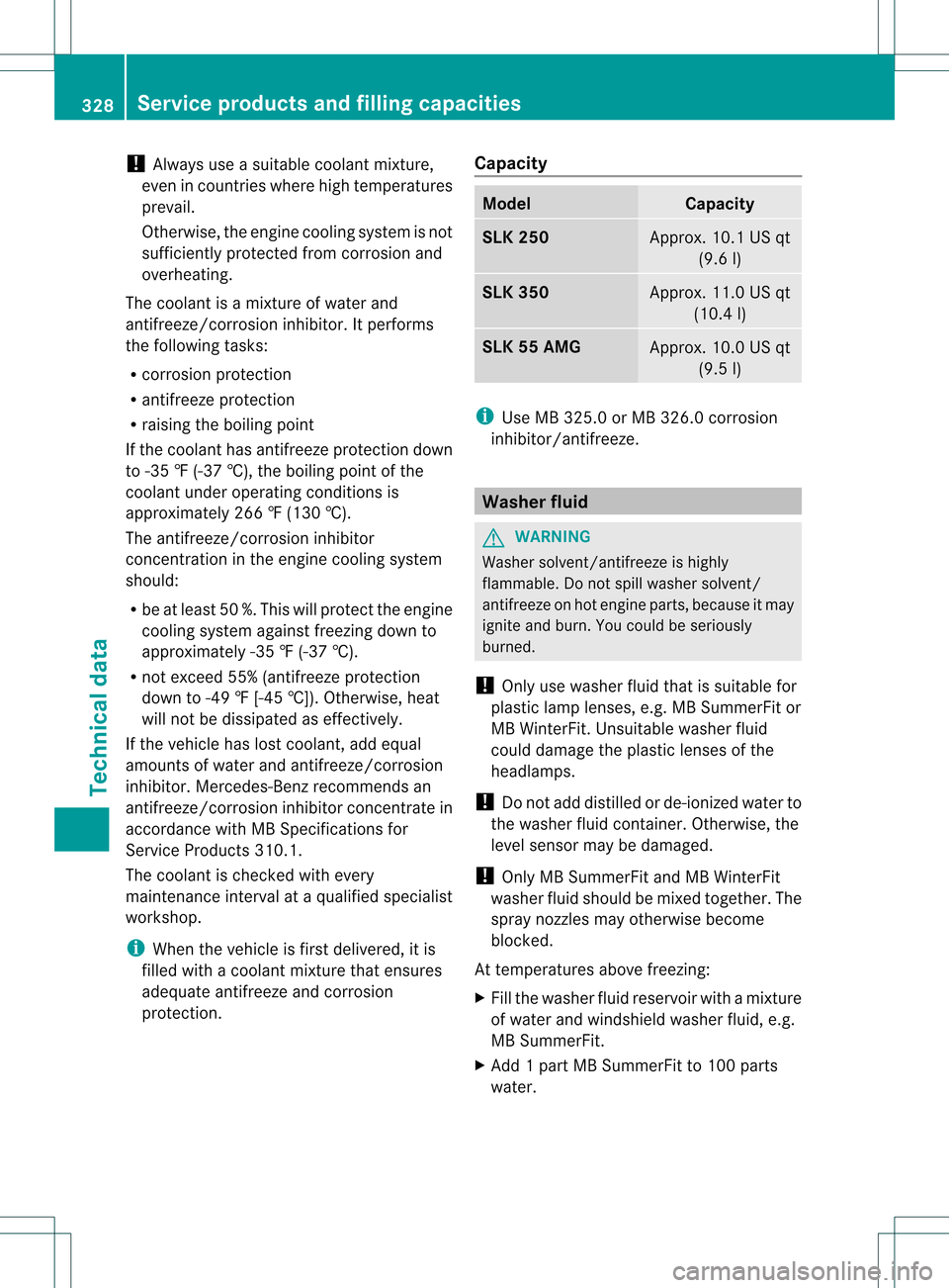
protection. Capacity Model Capacity
SLK 250
Approx. 10.1 US qt
(9.6 l) SLK 350
Approx. 11.0 US qt
(10.4 l) SLK 55 AMG
Approx. 10.0 US qt
(9.5 l) i
Use MB 325.0 or MB 326.0 corrosion
inhibitor/antifreeze. Washer fluid
G
WARNING
Washer solvent/antifreeze is highly
flammable. Do not spill washer solvent/
antifreeze on hot engine parts, because it may
ignite and burn. You could be seriously
burned.
! Only use washer fluid that is suitable for
plastic lamp lenses, e.g. MB SummerFit or
MB WinterFit. Unsuitable washer fluid
could damage the plastic lenses of the
headlamps.
! Do not add distilled or de-ionized water to
the washer fluid container. Otherwise, the
level sensor may be damaged.
! Only MB SummerFit and MB WinterFit
washer fluid should be mixed together. The
spray nozzles may otherwise become
blocked.
At temperatures above freezing:
X Fill the washer fluid reservoir with a mixture
of water and windshield washer fluid, e.g.
MB SummerFit.
X Add 1 part MB SummerFit to 100 parts
water. 328
Service products and filling capacitiesTechnical data