2012 MERCEDES-BENZ GLK SUV parking brake
[x] Cancel search: parking brakePage 223 of 381
Coupling up a trailer
G
WARNING
If you uncouple a trailer with an engaged over-
run brake, you could trap your hand between
the vehicle and the trailer drawbar. This poses
a risk of injury.
Do not uncouple a trailer with an engaged
overrun brake.
X Make sure that the transmission is in posi-
tion P.
X Engage the parking brake.
X Position the trailer level behind the vehicle.
X Couple up the trailer.
X Establish the electric connection between
the vehicle and the trailer.
X Check that the trailer lighting system is
working. Uncoupling a trailer
G
WARNING
Vehicles with level control:
If you disconnect the trailer cable, the vehicle
is lowered. This can cause you or others to
become trapped between the vehicle body
and tyres, or underneath the vehicle. This
poses a risk of injury.
Make sure that no-one is in the immediate
vicinity of the wheel arch or underneath the
vehicle when disconnecting the trailer cable.
! Do not disconnect a trailer with an
engaged overrun brake. Otherwise, your
vehicle could be damaged by the rebound-
ing of the overrun brake.
X Make sure that the transmission is in posi-
tion P.
X Engage the parking brake.
X Secure the trailer against rolling away.
X Remove the trailer cable and decouple the
trailer. Removing the ball coupling
X Pull the protective cap off the lock in the
handwheel.
X Use the key to unlock the lock in the hand-
wheel.
X Hold the ball coupling. Pull the handwheel
away from the ball coupling and turn it
clockwise until it engages.
The green area on the ball coupling is
aligned with the red mark on the hand-
wheel.
X Pull the ball coupling downwards to
remove.
X Clean the ball coupling if it is dirty.
Information on cleaning and care of the trailer
tow hitch can be found under (Y page 321). Storing the ball coupling
G
WARNING
Never transport an unsecured ball coupling in
the interior of the vehicle.
Otherwise, vehicle occupants could be
injured by the ball coupling being thrown if
you:
R brake sharply
R change direction suddenly
R have an accident
X Open the stowage well under the luggage
compartment floor.
X Remove the cover from the ball coupling
recess.
X Remove the protective cap from the ball
coupling recess.
X Press the protective cap into the ball cou-
pling recess until it engages.
X Make sure that the protective cap is firmly
in place.
X Store the ball coupling with the key inser-
ted in the ball coupling recess. 220
Towing a trailerDriving and parking
Page 240 of 381
X
Press the =or; button on the steer-
ing wheel to select the Assist.
Assist. menu.
X Press the 9or: button to select
Distance display
Distance display .
X Press the abutton.
The DISTRONIC PLUS distance display
(Y page 184) appears in the multifunction
display.
If the Sensors deactivated
Sensors deactivated message
appears, the radar sensor system is deacti-
vated.
X Check whether or not the radar sensor sys-
tem may be activated (Y page 375).
X Switch on the radar sensor system
(Y page 242).
Activating/deactivating PRE-SAFE ®
Brake PRE-SAFE
®
Brake is only available in vehicles
with DISTRONIC PLUS.
X Press the =or; button on the steer-
ing wheel to select the Assist. Assist.menu.
X Press the 9or: button to select
PRE-SAFE Brake
PRE-SAFE Brake .
X Press the abutton.
The current selection is displayed.
X To activate/deactivate: press thea
button again.
When PRE-SAFE ®
Brake (Y page 69) is acti-
vated, the multifunction display shows the
Ä symbol as long as the HOLD function is
not activated (Y page 186).
Vehicles with Parking Guidance: if PARK-
TRONIC is activated and you are driving at a
speed below 35 km/h, the jParking Guid-
ance symbol is shown instead of the Ä
symbol.
If the PRE-SAFE Brake: Sensors deacti‐ PRE-SAFE Brake: Sensors deacti‐
vated
vated message appears, the radar sensor
system is deactivated. X
Check whether or not the radar sensor sys-
tem may be activated (Y page 375).
X Switch on the radar sensor system
(Y page 242).
For more information on PRE-SAFE ®
Brake,
see (Y page 69).
Activating/deactivating ATTENTION
ASSIST X
Press the =or; button on the steer-
ing wheel to select the Assist. Assist.menu.
X Press the 9or: button to select
Attention Assist Attention Assist .
X Press the abutton.
The current selection is displayed.
X To activate/deactivate: press thea
button again.
When ATTENTION ASSIST (Y page 201) is
activated, the Àsymbol appears in the
multifunction display when the ignition is on.
For further information about ATTENTION
ASSIST, see (Y page 201).
Activating/deactivating Blind Spot
Assist X
Press the =or; button on the steer-
ing wheel to select the Assist. Assist.menu.
X Press the 9or: button to select
Blind Spot Asst.
Blind Spot Asst. .
X Press the abutton.
The current selection is displayed.
X To activate/deactivate: press thea
button again.
If the Blind Spot Assist Sensors deac‐
Blind Spot Assist Sensors deac‐
tivated
tivated orActive blind spot assist.
Active blind spot assist.
sensor system deactivated
sensor system deactivated message
appears, the radar sensor system is deacti-
vated.
X Check whether or not the radar sensor sys-
tem may be activated (Y page 375).
X Switch on the radar sensor system
(Y page 242). Displays and operation (12-button multifunction steering wheel)
237On-board computer and displays Z
Page 245 of 381
Activating/deactivating the acoustic
locking confirmation
If you switch on the Acoustic
Acoustic Lock Lockfunction,
an acoustic signal sounds when you lock the
vehicle.
X Press the =or; button on the steer-
ing wheel to select the Settings Settingsmenu.
X Press the :or9 button to select the
Vehicle
Vehicle submenu.
X Press ato confirm.
X Press the :or9 button to select the
Acoustic Lock
Acoustic Lock function.
If the Acoustic
Acoustic Lock
Lockfunction is activated,
the & symbol in the multifunction dis-
play lights up red.
X Press the abutton to save the setting.
Activating/deactivating the radar sensor
system
X Press the =or; button on the steer-
ing wheel to select the Settings
Settings menu.
X Press the :or9 button to select the
Vehicle Vehicle submenu.
X Press ato confirm.
X Press the 9or: button to select
Radar sensor (See Owner's Man.):
Radar sensor (See Owner's Man.): .
You will see the selected setting: Activa‐
Activa‐
ted
ted orDeactivated
Deactivated .
X Press the abutton to save the setting.
i You must deactivate the radar sensor sys-
tem in certain countries and near radio
telescope facilities. For further informa-
tion, see (Y page 375).
When you are close to radio telescope facili-
ties, the radar sensor system will be deacti-
vated automatically.
The following systems are switched off when
the radar sensor system is deactivated:
R DISTRONIC PLUS (Y page 178)
R BAS PLUS (Y page 66)
R PRE-SAFE ®
Brake (Y page 69)
R Active Blind Spot Assist (Y page 207)Heating Auxiliary heating departure time
Only vehicles with auxiliary heating
(Y
page 137) have this function.
In the Heating Heating submenu, you can select a
stored departure time or change a departure
time.
The auxiliary heating timer function calcu-
lates the switch-on time according to the out-
side temperature so that the vehicle is pre-
heated by the departure time. When the
departure time is reached, the auxiliary heat-
ing continues to heat for a further five
minutes and then switches off. The auxiliary
heating adopts the THERMATIC or
THERMOTRONIC temperature setting.
You can switch off the auxiliary heating by
using the remote control or the auxiliary heat-
ing button on the centre console. G
WARNING
Exhaust fumes are produced when the auxili-
ary heating is in operation. Inhaling these
exhaust fumes can be poisonous. You should
therefore switch off the auxiliary heating in
confined spaces without an extraction sys-
tem, e.g. a garage. G
WARNING
When operating the auxiliary heating parts of
the vehicle can get very hot. Make sure that
the exhaust system does not under any cir-
cumstances come into contact with easily
ignitable material such as dry grass or fuels.
The material could otherwise ignite and set
the vehicle alight. Choose your parking spot
accordingly.
Operating the auxiliary heating is thus pro-
hibited at filling stations or when your vehicle
is being refuelled. You must therefore switch
off the auxiliary heating at filling stations.
! Operating the auxiliary heating/ventila-
tion draws on the vehicle battery. After you
have heated or ventilated the vehicle a 242
Displays and operation (12-button multifunction steering wheel)On-board computer and displays
Page 251 of 381
Display messages Possible causes/consequences and
M
MSolutions ABS
ABS
inoperative
inoperative ABS, ESP
®
, BAS, PRE-SAFE ®
, hill start assist and ESP ®
trailer sta-
bilisation are not available due to a malfunction.
The adaptive brake lights may also have failed.
In addition, the ä,å,!andJ warning lamps light
up in the instrument cluster.
G WARNING
The brake system continues to function normally, but without the
functions listed above. The wheels could therefore lock if you
brake hard, for example.
The steerability and braking characteristics may be severely affec-
ted. The braking distance in an emergency braking situation can
increase.
If ESP ®
is not operational, ESP ®
is unable to stabilise the vehicle.
The danger of skidding and having an accident increases.
X Drive on carefully.
X Visit a qualified specialist workshop. EBD and ABS EBD and ABS
inoperative inoperative
EBD (electronic brake force distribution), ABS, ESP
®
, BAS, PRE-
SAFE ®
, the HOLD function, hill start assist and ESP ®
trailer stabi-
lisation are unavailable due to a malfunction.
The adaptive brake lights may also have failed.
In addition, the ä,åand! warning lamps light up in
the instrument cluster and a warning tone sounds.
G WARNING
The brake system continues to function normally, but without the
functions listed above. The front and rear wheels could therefore
lock if you brake hard, for example.
The steerability and braking characteristics may be severely affec-
ted. The braking distance in an emergency braking situation can
increase.
If ESP ®
is not operational, ESP ®
is unable to stabilise the vehicle.
The danger of skidding and having an accident increases.
X Drive on carefully.
X Visit a qualified specialist workshop immediately. J
Release parking Release parking
brake brake You are driving with the parking brake applied. A warning tone also
sounds.
X
Release the parking brake. 248
Display
messagesOn-board computer and displays
Page 256 of 381
Display messages Possible causes/consequences and
M
MSolutions The brake system continues to function normally, but without the
functions listed above.
The braking distance in an emergency braking situation can thus
increase.
If ESP
®
is not operational, ESP ®
is unable to stabilise the vehicle.
The danger of skidding and having an accident increases.
X Carefully drive on a suitable stretch of road, making slight steer-
ing movements at a speed above 20 km/h.
If the display message disappears, the functions mentioned
above are available again.
If the display message continues to be displayed:
X Drive on carefully.
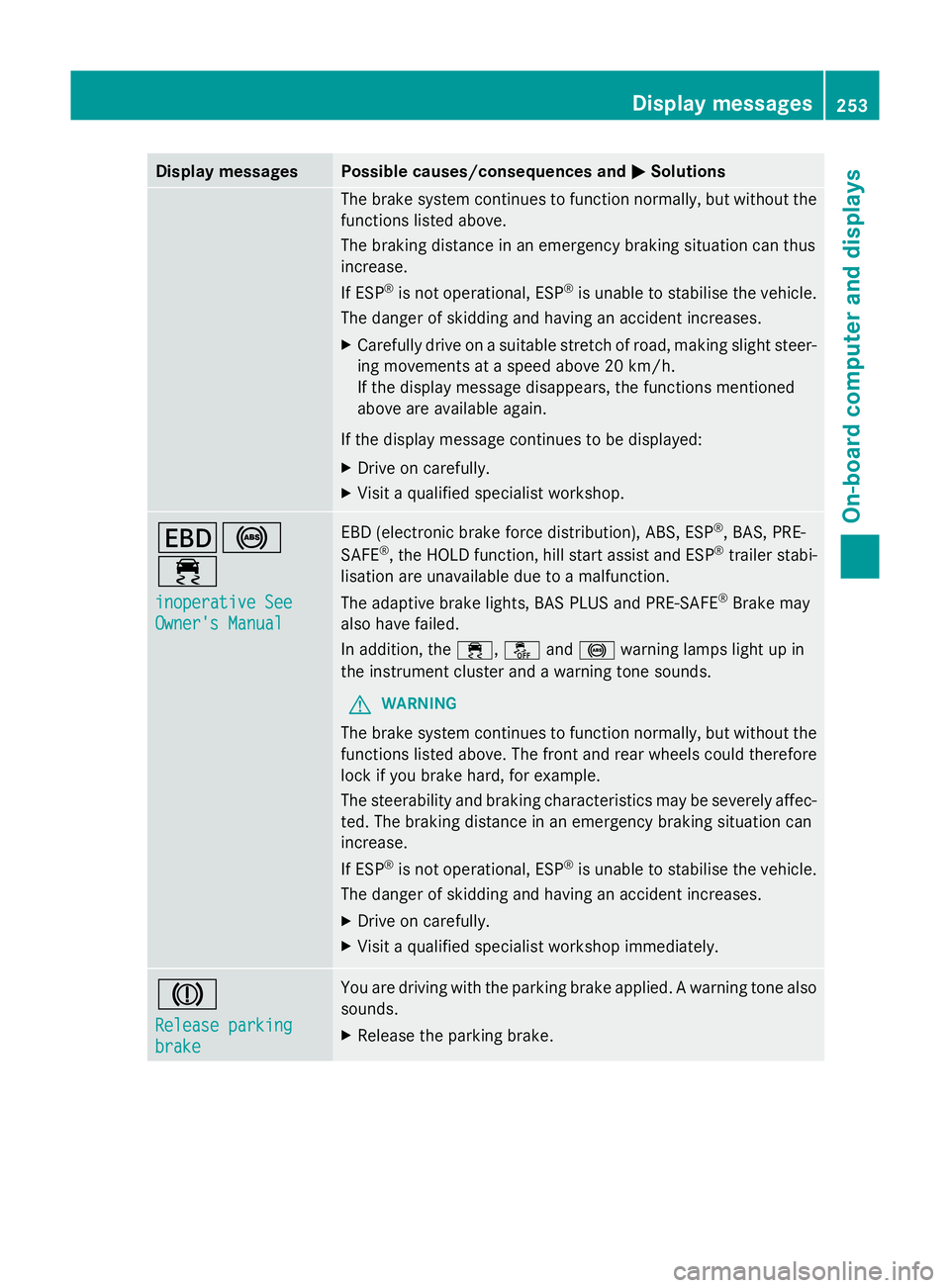
X Visit a qualified specialist workshop. T!
÷
inoperative See inoperative See
Owner's Manual Owner's Manual EBD (electronic brake force distribution), ABS, ESP
®
, BAS, PRE-
SAFE ®
, the HOLD function, hill start assist and ESP ®
trailer stabi-
lisation are unavailable due to a malfunction.
The adaptive brake lights, BAS PLUS and PRE-SAFE ®
Brake may
also have failed.
In addition, the ÷,åand! warning lamps light up in
the instrument cluster and a warning tone sounds.
G WARNING
The brake system continues to function normally, but without the
functions listed above. The front and rear wheels could therefore
lock if you brake hard, for example.
The steerability and braking characteristics may be severely affec-
ted. The braking distance in an emergency braking situation can
increase.
If ESP ®
is not operational, ESP ®
is unable to stabilise the vehicle.
The danger of skidding and having an accident increases.
X Drive on carefully.
X Visit a qualified specialist workshop immediately. J
Release parking Release parking
brake brake You are driving with the parking brake applied. A warning tone also
sounds.
X
Release the parking brake. Display
messages
253On-board computer and displays Z
Page 294 of 381
Problem Possible causes/consequences and
M
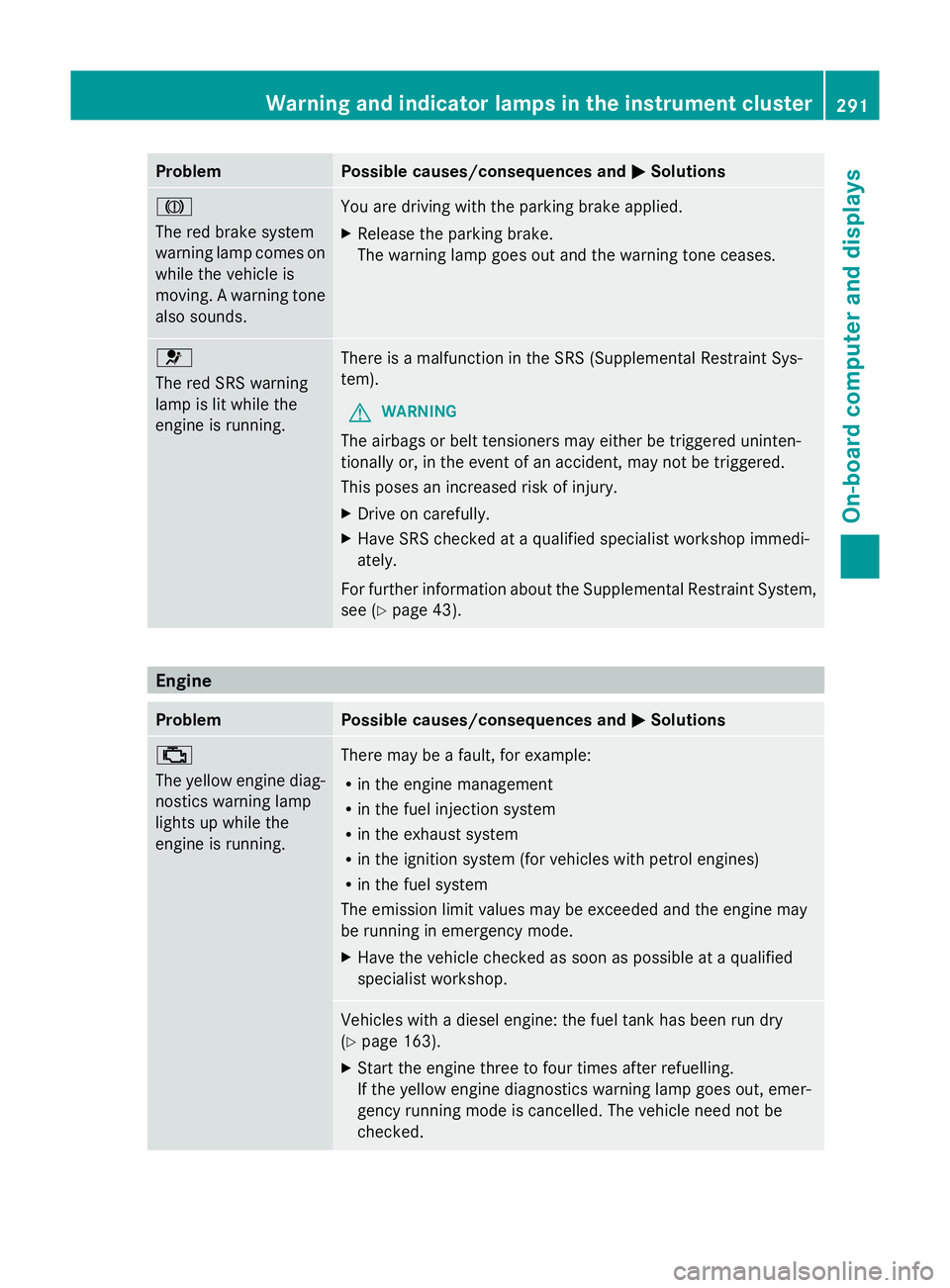
MSolutions J
The red brake system
warning lamp comes on
while the vehicle is
moving. A warning tone
also sounds.
You are driving with the parking brake applied.
X
Release the parking brake.
The warning lamp goes out and the warning tone ceases. 6
The red SRS warning
lamp is lit while the
engine is running.
There is a malfunction in the SRS (Supplemental Restraint Sys-
tem).
G WARNING
The airbags or belt tensioners may either be triggered uninten-
tionally or, in the event of an accident, may not be triggered.
This poses an increased risk of injury.
X Drive on carefully.
X Have SRS checked at a qualified specialist workshop immedi-
ately.
For further information about the Supplemental Restraint System,
see (Y page 43). Engine
Problem Possible causes/consequences and
M MSolutions ;
The yellow engine diag-
nostics warning lamp
lights up while the
engine is running.
There may be a fault, for example:
R
in the engine management
R in the fuel injection system
R in the exhaust system
R in the ignition system (for vehicles with petrol engines)
R in the fuel system
The emission limit values may be exceeded and the engine may
be running in emergency mode.
X Have the vehicle checked as soon as possible at a qualified
specialist workshop. Vehicles with a diesel engine: the fuel tank has been run dry
(Y
page 163).
X Start the engine three to four times after refuelling.
If the yellow engine diagnostics warning lamp goes out, emer-
gency running mode is cancelled. The vehicle need not be
checked. Warning and indicator lamps in the instrument cluster
291On-board computer and displays Z
Page 332 of 381
i
Fully deflating the tyre may take a few
minutes.
X Screw the valve insert back into the valve.
X Screw the valve cap back on.
X Place the valve extractor back into the vehi-
cle tool kit.
X Stow the collapsible emergency spare
wheel in the emergency spare wheel well
under the luggage compartment and fasten
in place. Flat tyre
Preparing the vehicle
Your vehicle may be equipped with:
R a TIREFIT kit
R an emergency spare wheel
X Stop the vehicle as far away as possible
from traffic on solid, non-slippery and level
ground.
X Switch on the hazard warning lamps.
X Firmly depress the parking brake.
X Bring the front wheels into the straight-
ahead position.
X Vehicles with manual transmission:
engage first or reverse gear.
X Vehicles with automatic transmission:
move the DIRECT SELECT lever to P.
X Switch off the engine.
X Vehicles without KEYLESS-GO: remove
the key from the ignition lock.
X Vehicles with KEYLESS-GO: open the
driver's door.
The on-board electronics have status 0,
which is the same as the key having been
removed.
X Vehicles with KEYLESS-GO: remove the
Start/Stop button from the ignition lock
(Y page 147). X
All occupants must get out of the vehicle.
Make sure that they are not endangered as
they do so.
X Make sure that no one is near the danger
area while a wheel is being changed. Any-
one who is not directly assisting in the
wheel change should, for example, stand
behind the barrier.
X Get out of the vehicle. Pay attention to traf-
fic conditions when doing so.
X Close the driver's door.
X Place the warning triangle (Y page 326) a
suitable distance away. Observe legal
requirements. TIREFIT kit
Using the TIREFIT kit TIREFIT is a tyre sealant.
You can use TIREFIT to seal punctures of up
to 4 mm, particularly those in the tyre tread.
You can use TIREFIT at outside temperatures
down to Ò20 †. G
WARNING
In the following situations, the tyre sealant is
unable to provide sufficient breakdown assis-
tance, as it is unable to seal the tyre properly:
R there are cuts or punctures in the tyre
larger than those mentioned above.
R the wheel rim is damaged.
R you have driven at very low tyre pressures
or on a flat tyre.
There is a risk of accident.
Do not drive any further. Contact a qualified
specialist workshop.
X Do not remove any foreign objects which
have penetrated the tyre, e.g. screws or
nails.
X Remove the tyre sealant bottle, the accom-
panying "max. 80 km/h" sticker and the
tyre inflation compressor from the stowage Flat tyre
329Breakdown assistance Z
Page 337 of 381
The following must be observed when raising
the vehicle:
R to raise the vehicle, only use the vehicle-
specific jack that has been tested and
approved by Mercedes-Benz. If the jack is
used incorrectly, it could tip over while the
vehicle is raised.
R the jack is designed only to raise and hold
the vehicle for a short time while a wheel
is being changed. It is not suited for per-
forming maintenance work under the vehi-
cle.
R avoid changing the wheel on uphill and
downhill slopes.
R before raising the vehicle, secure it from
rolling away by applying the parking brake
and inserting wheel chocks. Never disen-
gage the parking brake while the vehicle is
raised.
R the jack must be placed on a firm, flat and
non-slip surface. On a loose surface, a
large, load-bearing underlay must be used.
On a slippery surface, a non-slip underlay
must be used, e.g. rubber mats.
R do not use wooden blocks or similar
objects as a jack underlay. Otherwise, the
jack will not be able to achieve its load-
bearing capacity due to the restricted
height.
R make sure that the distance between the
underside of the tyres and the ground does
not exceed 3 cm.
R never place your hands or feet under the
raised vehicle.
R never lie under the raised vehicle.
R never start the engine when the vehicle is
raised.
R never open or close a door or the tailgate
when the vehicle is raised.
R make sure that no persons are present in
the vehicle when the vehicle is raised. X
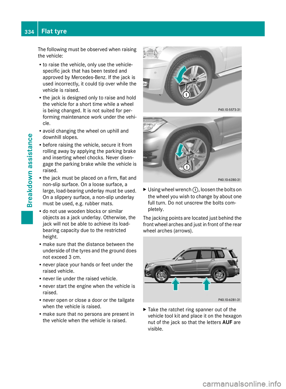
Using wheel wrench :, loosen the bolts on
the wheel you wish to change by about one
full turn. Do not unscrew the bolts com-
pletely.
The jacking points are located just behind the
front wheel arches and just in front of the rear
wheel arches (arrows). X
Take the ratchet ring spanner out of the
vehicle tool kit and place it on the hexagon
nut of the jack so that the letters AUFare
visible. 334
Flat tyreBreakdown assistance