2012 MERCEDES-BENZ GL lock
[x] Cancel search: lockPage 273 of 384
equipped, always use the cargo net when
transporting cargo.
Unless you are transporting cargo, the seat
backrests must remain properly locked in the
upright position.
In an accident, during hard braking or sudden
maneuvers, loose items will be thrown around
inside the vehicle. This can cause injury to
vehicle occupants unless the items are
securely fastened in the vehicle.
Always use the cargo tie-down rings.GWARNING
Never drive a vehicle with the tailgate open.
Deadly carbon monoxide (CO) gases may
enter vehicle interior resulting in
unconsciousness and death.
! Release and fold the seat cushion
upwards before folding the rear bench seat
forward. Otherwise, the backrests may be
damaged.
When the backrest is folded forwards, the
front seats cannot be moved to their
rearmost position. Otherwise, the front
seats and the rear bench seat could be
damaged.
The left-hand and right-hand backrests in the
second row of seats can be folded forwards
separately to increase the cargo
compartment capacity. On vehicles with a
third row of seats, you must fold down the
third row of seats beforehand (Y page 104) to
obtain maximum cargo compartment
enlargement.
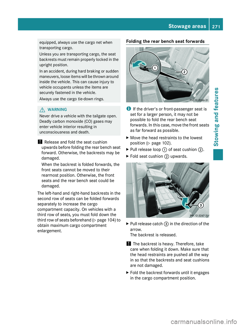
Folding the rear bench seat forwards
i If the driver's or front-passenger seat is
set for a larger person, it may not be
possible to fold the rear bench seat
forwards. In this case, move the front seats
as far forward as possible.
XMove the head restraints to the lowest
position ( Y page 102).XPull release loop : of seat cushion ;.XFold seat cushion ; upwards.XPull release catch = in the direction of the
arrow.
The backrest is released.
! The backrest is heavy. Therefore, take
care when folding it down. Make sure that
the head restraints are pushed all the way
in so that the backrests and seat cushions
are not damaged.
XFold the backrest forwards until it engages
in the cargo compartment position.Stowage areas271Stowing and featuresZ
Page 278 of 384
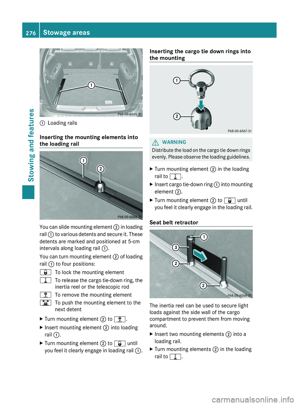
:Loading rails
Inserting the mounting elements into
the loading rail
You can slide mounting element ; in loading
rail : to various detents and secure it. These
detents are marked and positioned at 5-cm
intervals along loading rail :.
You can turn mounting element ; of loading
rail : to four positions:
&To lock the mounting element=To release the cargo tie-down ring, the
inertia reel or the telescopic rod;To remove the mounting elementBTo push the mounting element to the
next detentXTurn mounting element ; to ; .XInsert mounting element ; into loading
rail :.XTurn mounting element ; to & until
you feel it clearly engage in loading rail :.Inserting the cargo tie down rings into
the mountingGWARNING
Distribute the load on the cargo tie down rings
evenly. Please observe the loading guidelines.
XTurn mounting element ; in the loading
rail to =.XInsert cargo tie-down ring : into mounting
element ;.XTurn mounting element ; to & until
you feel it clearly engage in the loading rail.
Seat belt retractor
The inertia reel can be used to secure light
loads against the side wall of the cargo
compartment to prevent them from moving
around.
XInsert two mounting elements ; into a
loading rail.XTurn mounting elements ; in the loading
rail to =.276Stowage areasStowing and features
Page 279 of 384
XInsert inertia reel = into mounting
elements ;.XTurn mounting element ; to & until
you feel it clearly engage in the loading rail.XPress unlocking button : on inertia reel
= and pull the cargo net out in the
direction of the arrow.XPlace the load between the securing net
and the cargo compartment side wall.XUsing one hand, press locking button : of
inertia reel =.XWith your other hand, slowly extend the net
around the load until it is secure.
Telescopic rod
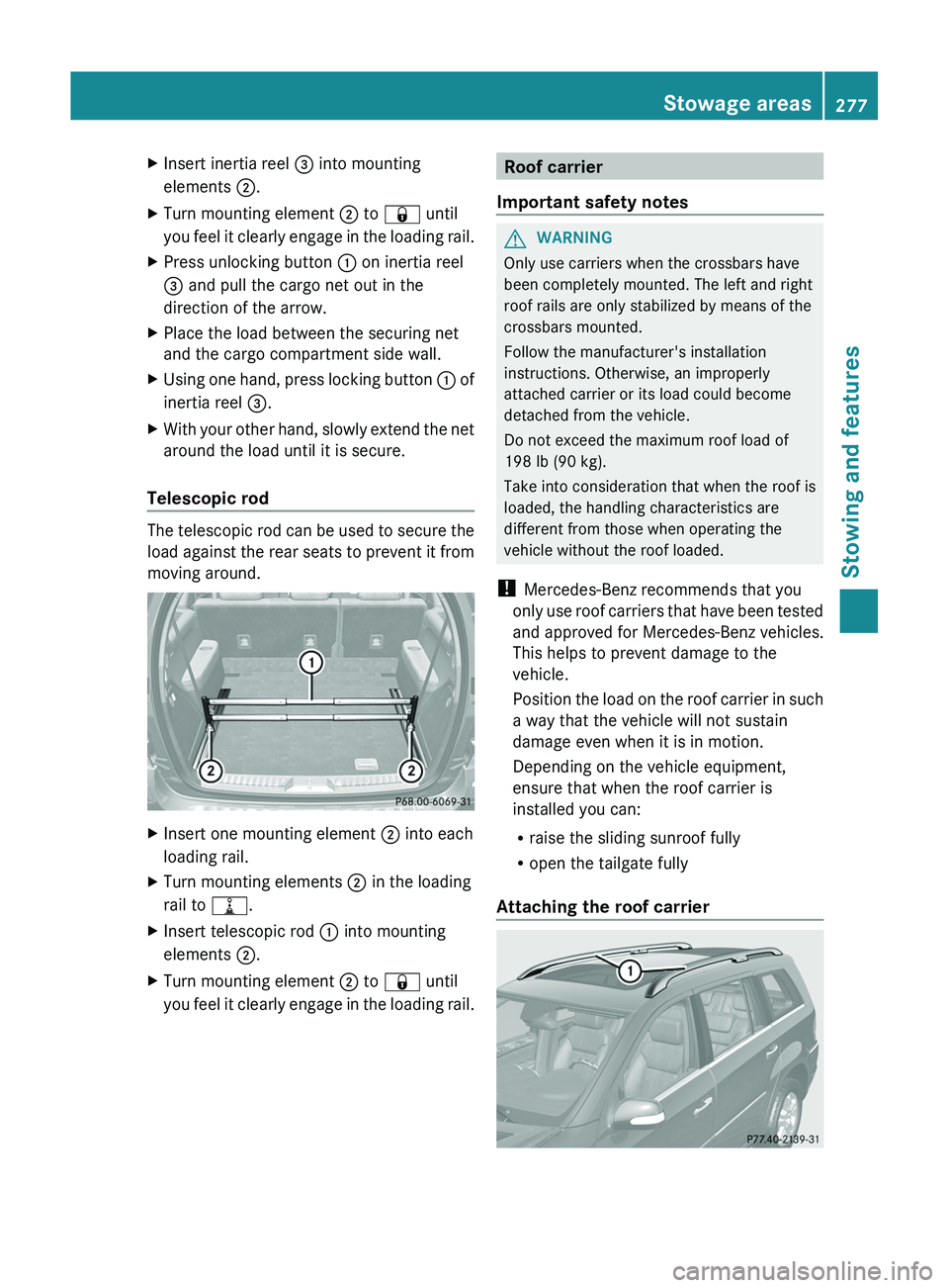
The telescopic rod can be used to secure the
load against the rear seats to prevent it from
moving around.
XInsert one mounting element ; into each
loading rail.XTurn mounting elements ; in the loading
rail to =.XInsert telescopic rod : into mounting
elements ;.XTurn mounting element ; to & until
you feel it clearly engage in the loading rail.Roof carrier
Important safety notesGWARNING
Only use carriers when the crossbars have
been completely mounted. The left and right
roof rails are only stabilized by means of the
crossbars mounted.
Follow the manufacturer's installation
instructions. Otherwise, an improperly
attached carrier or its load could become
detached from the vehicle.
Do not exceed the maximum roof load of
198 lb (90 kg).
Take into consideration that when the roof is
loaded, the handling characteristics are
different from those when operating the
vehicle without the roof loaded.
! Mercedes-Benz recommends that you
only use roof carriers that have been tested
and approved for Mercedes-Benz vehicles.
This helps to prevent damage to the
vehicle.
Position the load on the roof carrier in such
a way that the vehicle will not sustain
damage even when it is in motion.
Depending on the vehicle equipment,
ensure that when the roof carrier is
installed you can:
R raise the sliding sunroof fully
R open the tailgate fully
Attaching the roof carrier
Stowage areas277Stowing and featuresZ
Page 281 of 384
weight, even when accessories for the
crossbars (e.g. ski racks, bicycle racks, etc.)
are being used. Overloading the vehicle could
result in an accident. When calculating the
weight placed on the roof please make sure
to add the weight of the crossbars, accessory
racks and the load carried together.
Always adapt your driving style to the road,
traffic and weather conditions, and drive with
added caution when the roof is loaded.
Always drive with extreme care when the
carrier is loaded. Take into consideration that
when the carrier is loaded, the handling
characteristics are different from those when
operating the vehicle without a carrier loaded.GWARNING
Do not use accessories which have not been
approved by Mercedes-Benz for use in
conjunction with these crossbars. If non-
approved accessories are used, these
accessories and/or the objects attached to
them could come loose from the vehicle,
thereby injuring you and other persons and/
or causing damage to property, including
damage to your vehicle.
! Have a second person assist you when
installing the crossbars. Otherwise, the
vehicle could be damaged.
! Objects that are attached to crossbar
system accessories must not limit or
obstruct the movement of the sliding
sunroof. Otherwise, the tilt/sliding sunroof
could be damaged when it is raised.
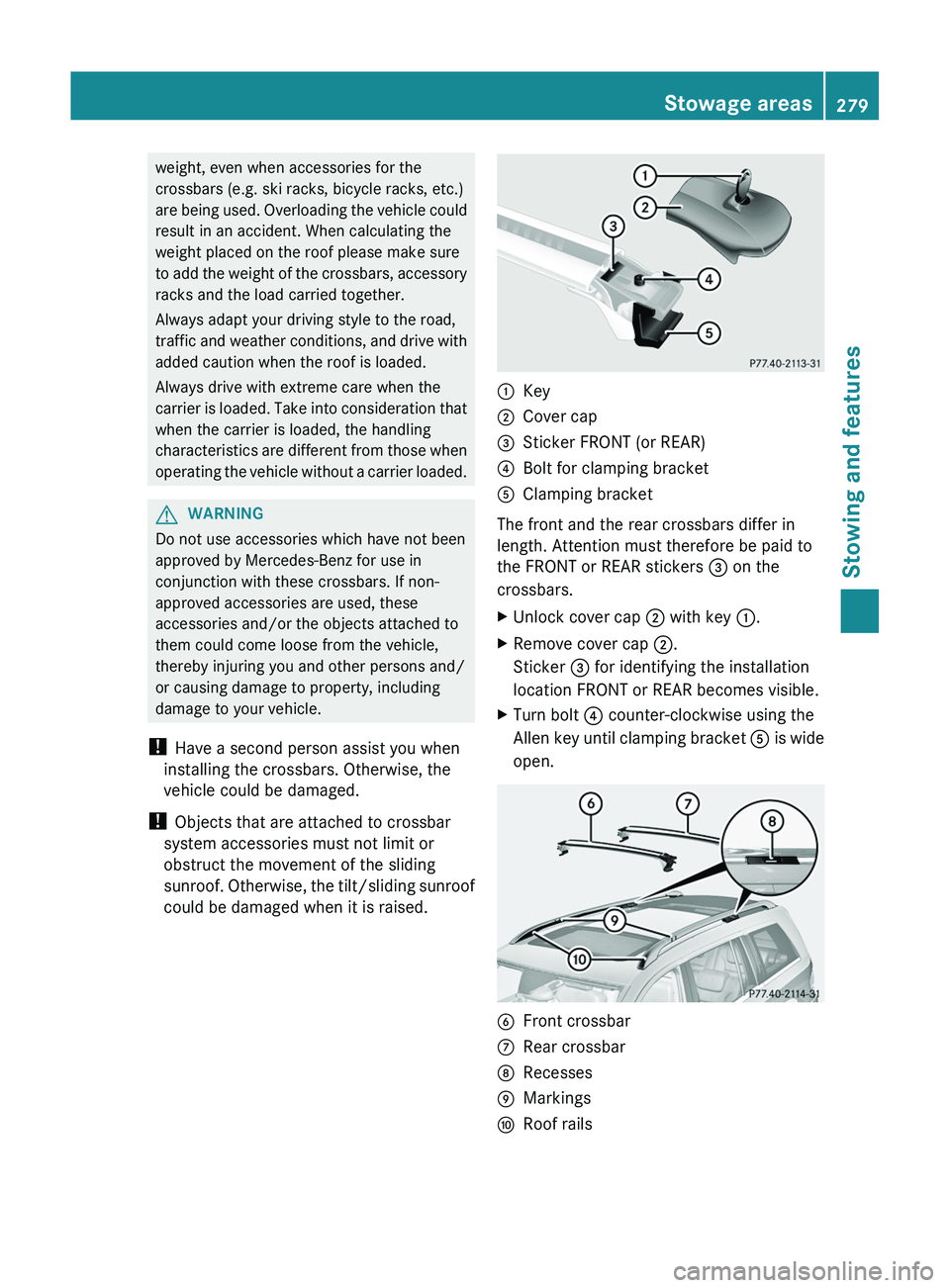
:Key;Cover cap=Sticker FRONT (or REAR)?Bolt for clamping bracketAClamping bracket
The front and the rear crossbars differ in
length. Attention must therefore be paid to
the FRONT or REAR stickers = on the
crossbars.
XUnlock cover cap ; with key :.XRemove cover cap ;.
Sticker = for identifying the installation
location FRONT or REAR becomes visible.XTurn bolt ? counter-clockwise using the
Allen key until clamping bracket A is wide
open.BFront crossbarCRear crossbarDRecessesEMarkingsFRoof railsStowage areas279Stowing and featuresZ
Page 282 of 384
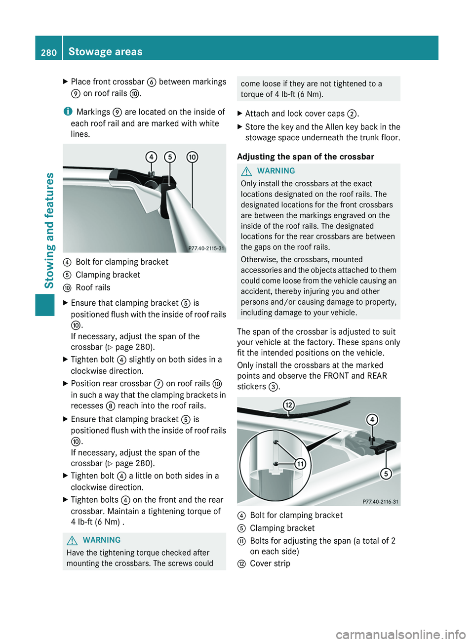
XPlace front crossbar B between markings
E on roof rails F.
i
Markings E are located on the inside of
each roof rail and are marked with white
lines.
?Bolt for clamping bracketAClamping bracketFRoof railsXEnsure that clamping bracket A is
positioned flush with the inside of roof rails
F .
If necessary, adjust the span of the
crossbar ( Y page 280).XTighten bolt ? slightly on both sides in a
clockwise direction.XPosition rear crossbar C on roof rails F
in such a way that the clamping brackets in
recesses D reach into the roof rails.XEnsure that clamping bracket A is
positioned flush with the inside of roof rails
F .
If necessary, adjust the span of the
crossbar ( Y page 280).XTighten bolt ? a little on both sides in a
clockwise direction.XTighten bolts ? on the front and the rear
crossbar. Maintain a tightening torque of
4 lb-ft (6 Nm) .GWARNING
Have the tightening torque checked after
mounting the crossbars. The screws could
come loose if they are not tightened to a
torque of 4 lb-ft (6 Nm).XAttach and lock cover caps ;.XStore the key and the Allen key back in the
stowage space underneath the trunk floor.
Adjusting the span of the crossbar
GWARNING
Only install the crossbars at the exact
locations designated on the roof rails. The
designated locations for the front crossbars
are between the markings engraved on the
inside of the roof rails. The designated
locations for the rear crossbars are between
the gaps on the roof rails.
Otherwise, the crossbars, mounted
accessories and the objects attached to them
could come loose from the vehicle causing an
accident, thereby injuring you and other
persons and/or causing damage to property,
including damage to your vehicle.
The span of the crossbar is adjusted to suit
your vehicle at the factory. These spans only
fit the intended positions on the vehicle.
Only install the crossbars at the marked
points and observe the FRONT and REAR
stickers =.
?Bolt for clamping bracketAClamping bracketGBolts for adjusting the span (a total of 2
on each side)HCover strip280Stowage areasStowing and features
Page 283 of 384
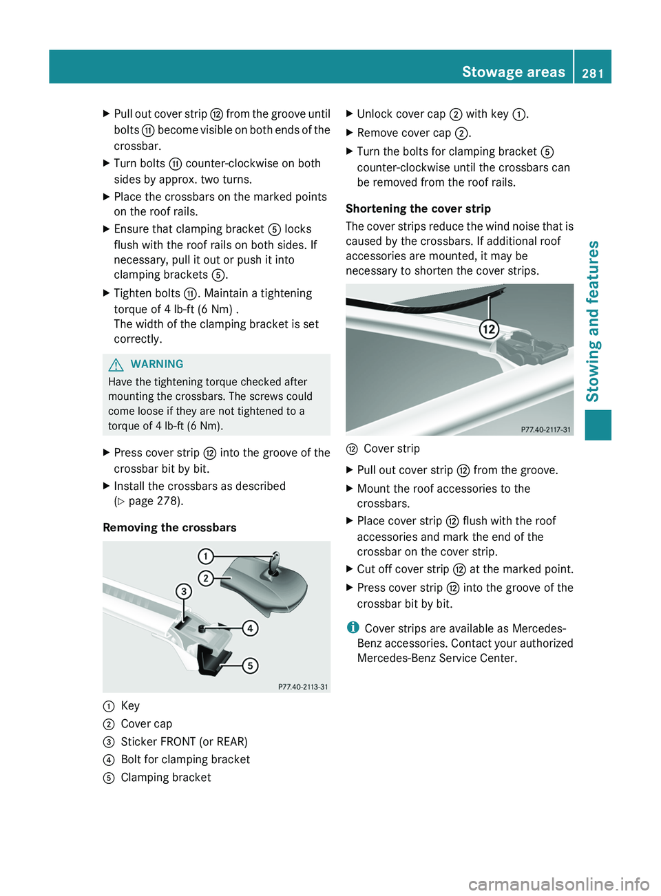
XPull out cover strip H from the groove until
bolts G become visible on both ends of the
crossbar.XTurn bolts G counter-clockwise on both
sides by approx. two turns.XPlace the crossbars on the marked points
on the roof rails.XEnsure that clamping bracket A locks
flush with the roof rails on both sides. If
necessary, pull it out or push it into
clamping brackets A.XTighten bolts G. Maintain a tightening
torque of 4 lb-ft (6 Nm) .
The width of the clamping bracket is set
correctly.GWARNING
Have the tightening torque checked after
mounting the crossbars. The screws could
come loose if they are not tightened to a
torque of 4 lb-ft (6 Nm).
XPress cover strip H into the groove of the
crossbar bit by bit.XInstall the crossbars as described
( Y page 278).
Removing the crossbars
:Key;Cover cap=Sticker FRONT (or REAR)?Bolt for clamping bracketAClamping bracketXUnlock cover cap ; with key :.XRemove cover cap ;.XTurn the bolts for clamping bracket A
counter-clockwise until the crossbars can
be removed from the roof rails.
Shortening the cover strip
The cover strips reduce the wind noise that is
caused by the crossbars. If additional roof
accessories are mounted, it may be
necessary to shorten the cover strips.
HCover stripXPull out cover strip H from the groove.XMount the roof accessories to the
crossbars.XPlace cover strip H flush with the roof
accessories and mark the end of the
crossbar on the cover strip.XCut off cover strip H at the marked point.XPress cover strip H into the groove of the
crossbar bit by bit.
i Cover strips are available as Mercedes-
Benz accessories. Contact your authorized
Mercedes-Benz Service Center.
Stowage areas281Stowing and featuresZ
Page 286 of 384
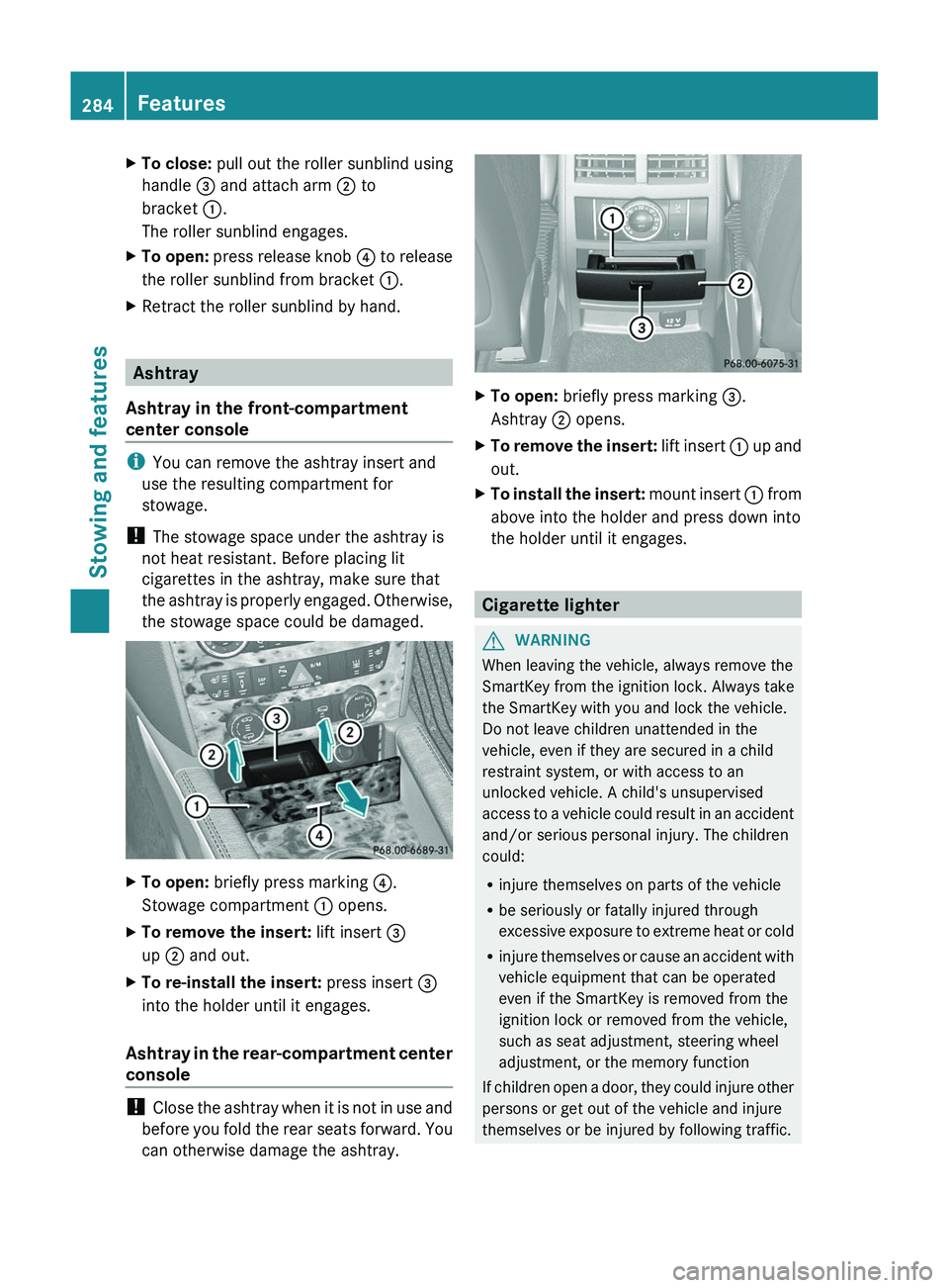
XTo close: pull out the roller sunblind using
handle = and attach arm ; to
bracket :.
The roller sunblind engages.XTo open: press release knob ? to release
the roller sunblind from bracket :.XRetract the roller sunblind by hand.
Ashtray
Ashtray in the front-compartment
center console
i You can remove the ashtray insert and
use the resulting compartment for
stowage.
! The stowage space under the ashtray is
not heat resistant. Before placing lit
cigarettes in the ashtray, make sure that
the ashtray is properly engaged. Otherwise,
the stowage space could be damaged.
XTo open: briefly press marking ?.
Stowage compartment : opens.XTo remove the insert: lift insert =
up ; and out.XTo re-install the insert: press insert =
into the holder until it engages.
Ashtray in the rear-compartment center
console
! Close the ashtray when it is not in use and
before you fold the rear seats forward. You
can otherwise damage the ashtray.
XTo open: briefly press marking =.
Ashtray ; opens.XTo remove the insert: lift insert : up and
out.XTo install the insert: mount insert : from
above into the holder and press down into
the holder until it engages.
Cigarette lighter
GWARNING
When leaving the vehicle, always remove the
SmartKey from the ignition lock. Always take
the SmartKey with you and lock the vehicle.
Do not leave children unattended in the
vehicle, even if they are secured in a child
restraint system, or with access to an
unlocked vehicle. A child's unsupervised
access to a vehicle could result in an accident
and/or serious personal injury. The children
could:
R injure themselves on parts of the vehicle
R be seriously or fatally injured through
excessive exposure to extreme heat or cold
R injure themselves or cause an accident with
vehicle equipment that can be operated
even if the SmartKey is removed from the
ignition lock or removed from the vehicle,
such as seat adjustment, steering wheel
adjustment, or the memory function
If children open a door, they could injure other
persons or get out of the vehicle and injure
themselves or be injured by following traffic.
284FeaturesStowing and features
Page 287 of 384
Do not expose the child restraint system to
direct sunlight. The child restraint system's
metal parts, for example, could become very
hot, and the child could be burned on these
parts.GWARNING
Never touch the heating element or sides of
the lighter; they are extremely hot. Hold the
knob only.
Make sure any children traveling with you do
not injure themselves or start a fire with the
hot cigarette lighter.
! The 12 V socket in the cigarette lighter
can be used for accessories (up to a
maximum of 180 W) as long as they have
the standard socket type for cigarette
lighters. Note that the socket in the
cigarette lighter can be damaged when
connecting accessories, for example by
frequent insertion and removal or by
sockets that do not fit correctly. A damaged
socket can cause the cigarette lighter to
stop working.
! The cigarette lighter in the center console
in the front compartment is not intended
for operating the tire inflation compressor.
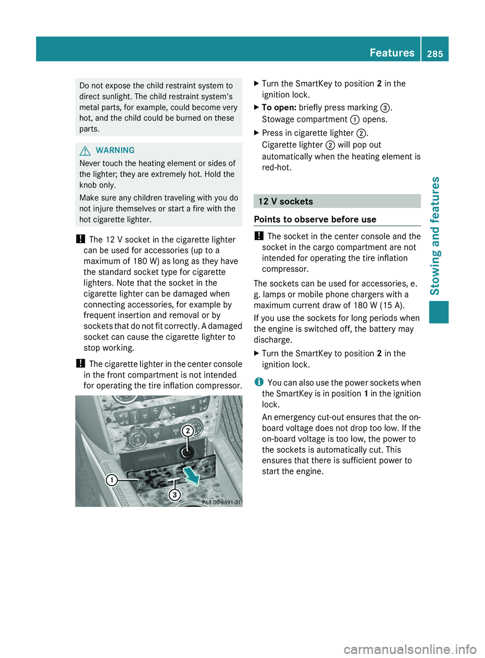
XTurn the SmartKey to position 2 in the
ignition lock.XTo open: briefly press marking =.
Stowage compartment : opens.XPress in cigarette lighter ;.
Cigarette lighter ; will pop out
automatically when the heating element is
red-hot.
12 V sockets
Points to observe before use
! The socket in the center console and the
socket in the cargo compartment are not
intended for operating the tire inflation
compressor.
The sockets can be used for accessories, e.
g. lamps or mobile phone chargers with a
maximum current draw of 180 W (15 A).
If you use the sockets for long periods when
the engine is switched off, the battery may
discharge.
XTurn the SmartKey to position 2 in the
ignition lock.
i You can also use the power sockets when
the SmartKey is in position 1 in the ignition
lock.
An emergency cut-out ensures that the on-
board voltage does not drop too low. If the
on-board voltage is too low, the power to
the sockets is automatically cut. This
ensures that there is sufficient power to
start the engine.
Features285Stowing and featuresZ