2012 MERCEDES-BENZ GL wheel
[x] Cancel search: wheelPage 267 of 384
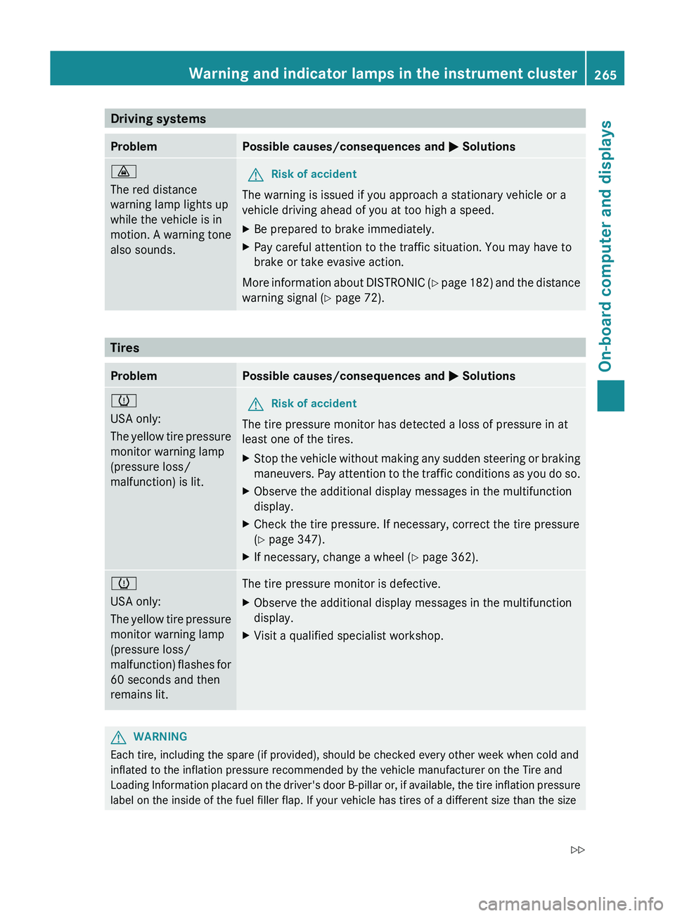
Driving systemsProblemPossible causes/consequences and M Solutions·
The red distance
warning lamp lights up
while the vehicle is in
motion. A warning tone
also sounds.GRisk of accident
The warning is issued if you approach a stationary vehicle or a
vehicle driving ahead of you at too high a speed.
XBe prepared to brake immediately.XPay careful attention to the traffic situation. You may have to
brake or take evasive action.
More information about DISTRONIC (Y page 182) and the distance
warning signal ( Y page 72).
Tires
ProblemPossible causes/consequences and M Solutionsh
USA only:
The yellow tire pressure
monitor warning lamp
(pressure loss/
malfunction) is lit.GRisk of accident
The tire pressure monitor has detected a loss of pressure in at
least one of the tires.
XStop the vehicle without making any sudden steering or braking
maneuvers. Pay attention to the traffic conditions as you do so.XObserve the additional display messages in the multifunction
display.XCheck the tire pressure. If necessary, correct the tire pressure
( Y page 347).XIf necessary, change a wheel ( Y page 362).h
USA only:
The yellow tire pressure
monitor warning lamp
(pressure loss/
malfunction) flashes for
60 seconds and then
remains lit.The tire pressure monitor is defective.XObserve the additional display messages in the multifunction
display.XVisit a qualified specialist workshop.GWARNING
Each tire, including the spare (if provided), should be checked every other week when cold and
inflated to the inflation pressure recommended by the vehicle manufacturer on the Tire and
Loading Information placard on the driver's door B-pillar or, if available, the tire inflation pressure
label on the inside of the fuel filler flap. If your vehicle has tires of a different size than the size
Warning and indicator lamps in the instrument cluster265On-board computer and displaysZ
Page 268 of 384
indicated on the Tire and Loading Information placard or, if available, the tire inflation pressure
label, you should determine the proper tire inflation pressure for those tires.
As an added safety feature, your vehicle has been equipped with a tire pressure monitoring
system (TPMS) that illuminates a low tire pressure warning lamp when one or more of your tires
are significantly underinflated. Accordingly, when the low tire pressure warning lamp illuminates,
you should stop and check your tires as soon as possible, and inflate them to the proper pressure.
Driving on a significantly underinflated tire causes the tire to overheat and can lead to tire failure.
Underinflation also reduces fuel efficiency and tire tread life, and may affect the vehicle's handling
and stopping ability. Please note that the TPMS is not a substitute for proper tire maintenance,
and it is the driver's responsibility to maintain correct tire pressure, even if underinflation has
not reached the level to trigger illumination of the TPMS low tire pressure warning lamp.
Your vehicle has also been equipped with a TPMS malfunction indicator to indicate when the
system is not operating properly. The TPMS malfunction indicator is combined with the low tire
pressure warning lamp. When the system detects a malfunction, the warning lamp will flash for
approximately one minute and then remain continuously illuminated. This sequence will continue
upon subsequent vehicle start-ups as long as the malfunction exists. When the malfunction
indicator is lit, the system may not be able to detect or signal low tire pressure as intended.
TPMS malfunctions may occur for a variety of reasons, including the installation of incompatible
replacement or alternate tires or wheels on the vehicle that prevent the TPMS from functioning
properly. Always check the TPMS malfunction warning lamp after replacing one or more tires or
wheels on your vehicle to ensure that the replacement or alternate tires and wheels allow the
TPMS to continue to function properly.266Warning and indicator lamps in the instrument clusterOn-board computer and displays
Page 270 of 384
Useful information
i This Operator's Manual describes all
models and all standard and optional
equipment of your vehicle available at the
time of publication of the Operator's
Manual. Country-specific differences are
possible. Please note that your vehicle may
not be equipped with all features
described. This also applies to safety-
related systems and functions.
i Please read the information on qualified
specialist workshops ( Y page 24).
Loading guidelines
GWARNING
Always fasten items being carried as securely
as possible. Use cargo tie-down rings and
fastening materials appropriate for the weight
and size of the load.
In an accident, during hard braking or sudden
maneuvers, loose items will be thrown around
inside the vehicle. This can cause injury to
vehicle occupants unless the items are
securely fastened in the vehicle.
To help avoid personal injury during a collision
or sudden maneuver, exercise care when
transporting cargo. Do not pile luggage or
cargo higher than the seat backrests.
The cargo compartment is the preferred place
to carry objects. Always use cargo tie-down
rings, and if so equipped, always use the cargo
net when transporting cargo.
Never drive a vehicle with the tailgate open.
Deadly carbon monoxide (CO) gases may
enter vehicle interior resulting in
unconsciousness and death.
The gross vehicle weight (GVW) is the vehicle
weight including fuel, vehicle tool kit, spare
wheel, installed accessories, vehicle
occupants and luggage/cargo.
The gross load limit and the gross vehicle
weight rating (GVWR) for your vehicle must
never be exceeded. The gross load limit and
the GVWR are specified on the vehicle
identification plate on the B-pillar of the
driver's door ( Y page 349).
The load must also be distributed so that the
weight on each axle never exceeds the gross
axle weight rating (GAWR) for the front and
rear axles. The specifications for GVWR and
GAWR are on the vehicle identification plate
on the B-pillar of the driver's door
( Y page 349).
Further information can be found in the
"Loading the vehicle" section ( Y page 349).
The handling characteristics of a laden
vehicle are dependent on the distribution of
the load within the vehicle. For this reason,
you should observe the following notes when
transporting a load:
R position heavy loads as far forwards as
possible and as low down in the cargo
compartment as possible.
R the load must not protrude above the upper
edge of the seat backrests.
R always place the load against the rear or
front seat backrests. Make sure that the
seat backrests are securely locked into
place.
R hook in the cargo net when loading.
R always place the load behind unoccupied
seats if possible.
R secure the load with sufficiently strong and
wear-resistant tie down. pad sharp edges
for protection.
Stowage areas
Stowage compartments
Important safety notes
GWARNING
To help avoid personal injury during a collision
or sudden maneuver, exercise care when
storing objects in the vehicle. Put luggage or
cargo in the cargo compartment if possible.
268Stowage areasStowing and features
Page 286 of 384
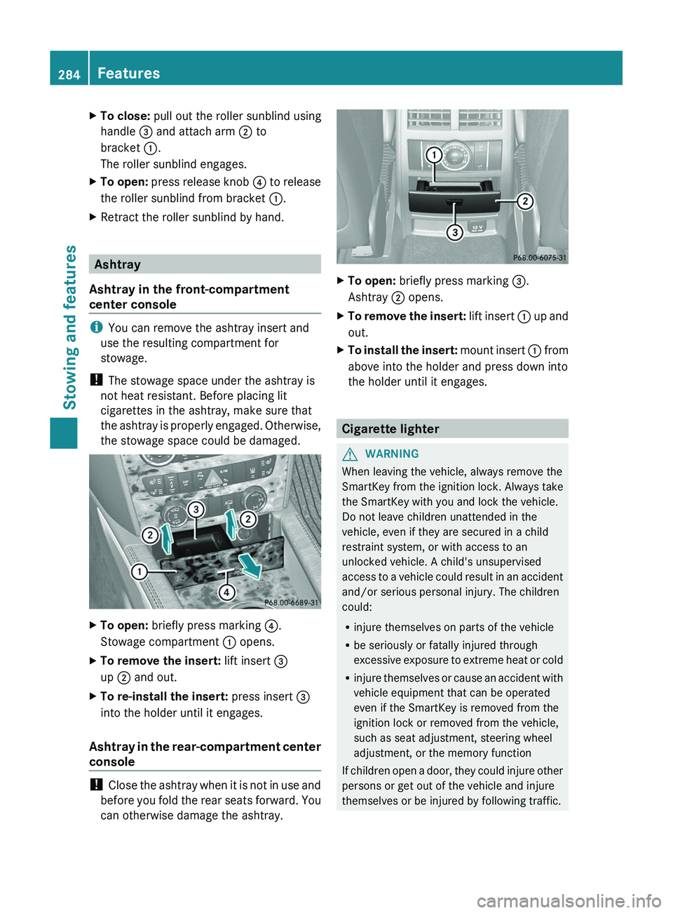
XTo close: pull out the roller sunblind using
handle = and attach arm ; to
bracket :.
The roller sunblind engages.XTo open: press release knob ? to release
the roller sunblind from bracket :.XRetract the roller sunblind by hand.
Ashtray
Ashtray in the front-compartment
center console
i You can remove the ashtray insert and
use the resulting compartment for
stowage.
! The stowage space under the ashtray is
not heat resistant. Before placing lit
cigarettes in the ashtray, make sure that
the ashtray is properly engaged. Otherwise,
the stowage space could be damaged.
XTo open: briefly press marking ?.
Stowage compartment : opens.XTo remove the insert: lift insert =
up ; and out.XTo re-install the insert: press insert =
into the holder until it engages.
Ashtray in the rear-compartment center
console
! Close the ashtray when it is not in use and
before you fold the rear seats forward. You
can otherwise damage the ashtray.
XTo open: briefly press marking =.
Ashtray ; opens.XTo remove the insert: lift insert : up and
out.XTo install the insert: mount insert : from
above into the holder and press down into
the holder until it engages.
Cigarette lighter
GWARNING
When leaving the vehicle, always remove the
SmartKey from the ignition lock. Always take
the SmartKey with you and lock the vehicle.
Do not leave children unattended in the
vehicle, even if they are secured in a child
restraint system, or with access to an
unlocked vehicle. A child's unsupervised
access to a vehicle could result in an accident
and/or serious personal injury. The children
could:
R injure themselves on parts of the vehicle
R be seriously or fatally injured through
excessive exposure to extreme heat or cold
R injure themselves or cause an accident with
vehicle equipment that can be operated
even if the SmartKey is removed from the
ignition lock or removed from the vehicle,
such as seat adjustment, steering wheel
adjustment, or the memory function
If children open a door, they could injure other
persons or get out of the vehicle and injure
themselves or be injured by following traffic.
284FeaturesStowing and features
Page 290 of 384
Shortly after successfully registering with the
mbrace service, a user ID and password will
be sent to you by post. You can use this
password to log in to the mbrace section
under "Owners Online" at http://
www.mbusa.com 32
.
The mbrace system is available if:
R it has been activated and is operational.
R the corresponding mobile phone network
is available for transmitting data to the
Customer Center.
R a service subscription is available.
R the starter battery is sufficiently charged.
i Determining the location of the vehicle on
a map is only possible if there is sufficient
GPS reception and the vehicle position can
be forwarded to the Customer Center.
The mbrace system
The mbrace system provides different
services, e.g.:
R automatic and manual emergency call
R Roadside Assistance call
R MB Info call
To adjust the volume during an mbrace call,
proceed as follows:
XPress the W or X button on the
multifunction steering wheel.
or
XUse the volume controller of COMAND.
You can find further information and a
description of all available features under
"Owners Online" at http://
www.mbusa.com 33
.
System self-test
After you have switched on the ignition, the
system carries out a self-diagnosis.
GWARNING
A malfunction in the system has been
detected if one of the following conditions
occurs:
R the indicator lamp in the SOS button does
not light up during the system self-
diagnosis.
R the indicator lamp in the º Roadside
Assistance button does not light up during
the system self-diagnosis.
R The indicator lamp in the E information
button does not light up during self-
diagnosis of the system.
R the indicator lamp in the SOS button,
º Roadside Assistance button or E
information button continues to be lit red
after the system self-diagnosis.
R The Tele Aid Inoperative or Tele Aid
Not Activated message appears in the
multifunction display after the system self-
test.
If a malfunction is indicated as outlined above,
the system may not operate as expected. In
the event of an emergency, assistance must
be summoned by other means.
Have the system checked at the nearest
authorized Mercedes-Benz Center or contact
the following service hotlines:
R USA: Response Center under
888-990-9007
R Canada: Customer Service at
1-888-923-8367
Emergency call
Important safety notes
! A license agreement must exist in order
to activate the mbrace service. Ensure that
your system is activated and ready for use,
and press the E MB Info call button to
register. If any of the steps mentioned is
32 USA only.
33 USA only.288FeaturesStowing and features
Page 292 of 384
Mercedes-Benz Customer Assistance Center
will automatically contact local emergency
officials with the vehicle's approximate
location if they receive an automatic SOS
signal and cannot make voice contact with the
vehicle occupants.
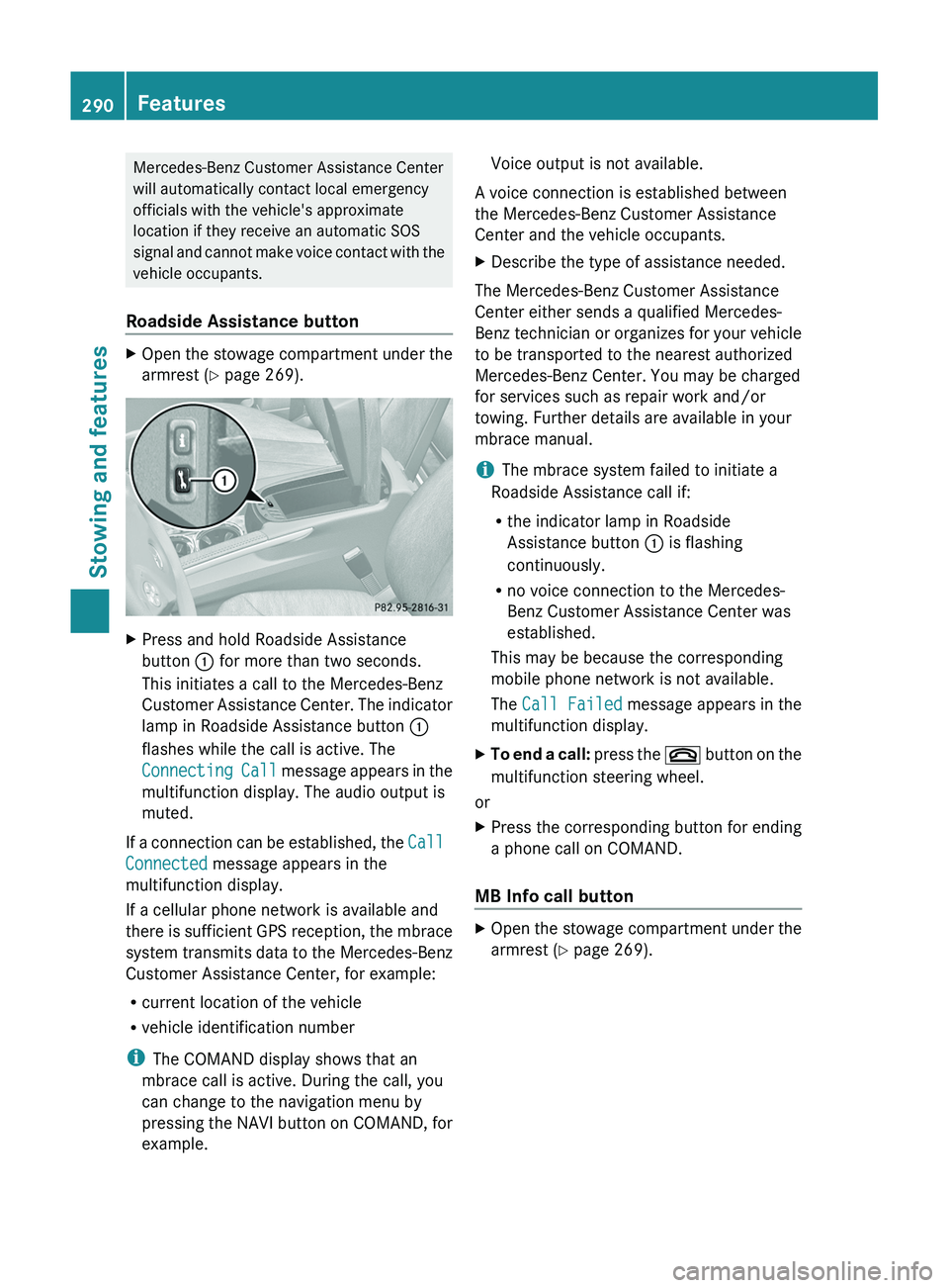
Roadside Assistance buttonXOpen the stowage compartment under the
armrest ( Y page 269).XPress and hold Roadside Assistance
button : for more than two seconds.
This initiates a call to the Mercedes-Benz
Customer Assistance Center. The indicator
lamp in Roadside Assistance button :
flashes while the call is active. The
Connecting Call message appears in the
multifunction display. The audio output is
muted.
If a connection can be established, the Call
Connected message appears in the
multifunction display.
If a cellular phone network is available and
there is sufficient GPS reception, the mbrace
system transmits data to the Mercedes-Benz
Customer Assistance Center, for example:
R current location of the vehicle
R vehicle identification number
i The COMAND display shows that an
mbrace call is active. During the call, you
can change to the navigation menu by
pressing the NAVI button on COMAND, for
example.
Voice output is not available.
A voice connection is established between
the Mercedes-Benz Customer Assistance
Center and the vehicle occupants.XDescribe the type of assistance needed.
The Mercedes-Benz Customer Assistance
Center either sends a qualified Mercedes-
Benz technician or organizes for your vehicle
to be transported to the nearest authorized
Mercedes-Benz Center. You may be charged
for services such as repair work and/or
towing. Further details are available in your
mbrace manual.
i The mbrace system failed to initiate a
Roadside Assistance call if:
R the indicator lamp in Roadside
Assistance button : is flashing
continuously.
R no voice connection to the Mercedes-
Benz Customer Assistance Center was
established.
This may be because the corresponding
mobile phone network is not available.
The Call Failed message appears in the
multifunction display.
XTo end a call: press the ~ button on the
multifunction steering wheel.
or
XPress the corresponding button for ending
a phone call on COMAND.
MB Info call button
XOpen the stowage compartment under the
armrest ( Y page 269).290FeaturesStowing and features
Page 293 of 384
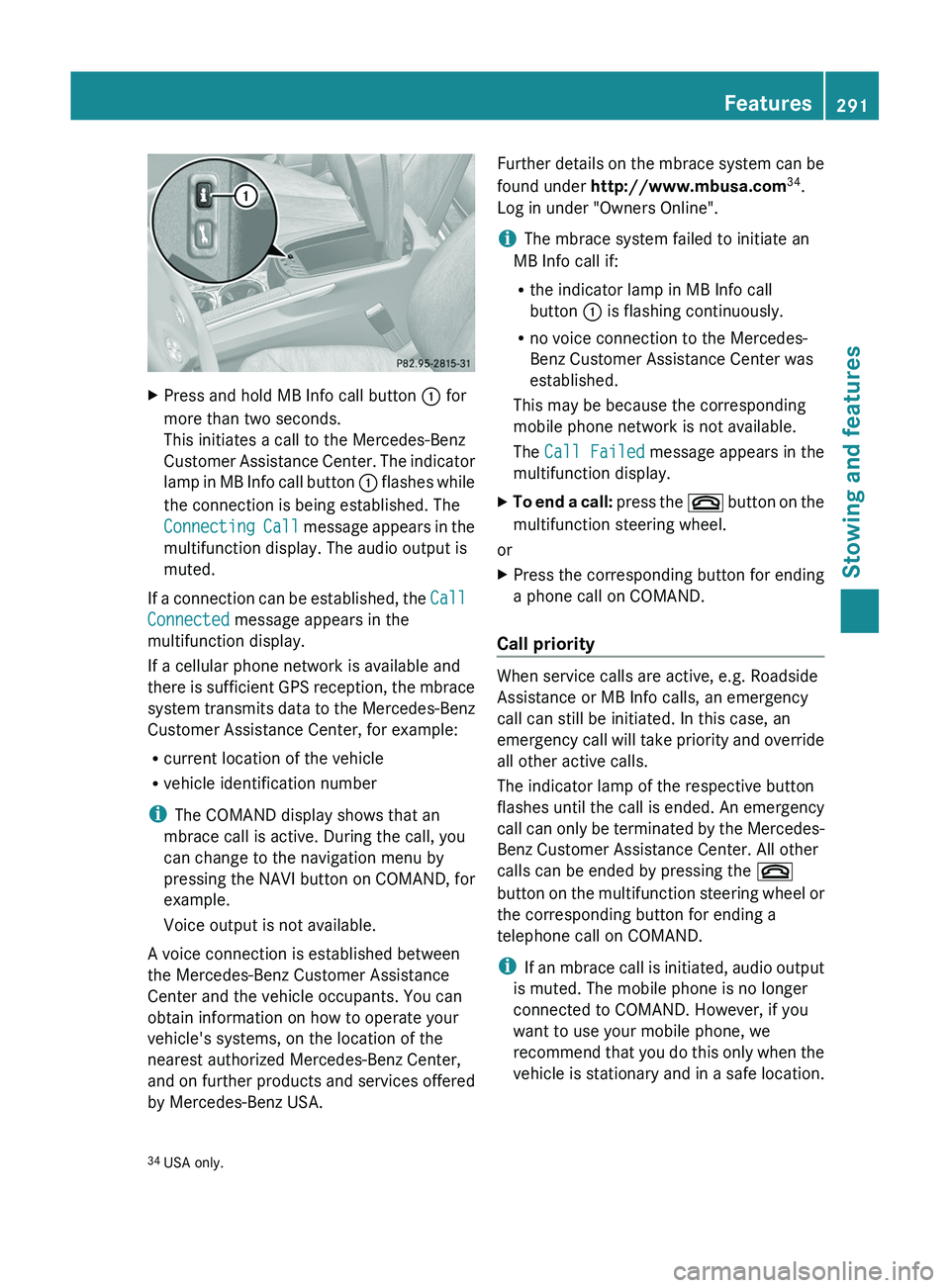
XPress and hold MB Info call button : for
more than two seconds.
This initiates a call to the Mercedes-Benz
Customer Assistance Center. The indicator
lamp in MB Info call button : flashes while
the connection is being established. The
Connecting Call message appears in the
multifunction display. The audio output is
muted.
If a connection can be established, the Call
Connected message appears in the
multifunction display.
If a cellular phone network is available and
there is sufficient GPS reception, the mbrace
system transmits data to the Mercedes-Benz
Customer Assistance Center, for example:
R current location of the vehicle
R vehicle identification number
i The COMAND display shows that an
mbrace call is active. During the call, you
can change to the navigation menu by
pressing the NAVI button on COMAND, for
example.
Voice output is not available.
A voice connection is established between
the Mercedes-Benz Customer Assistance
Center and the vehicle occupants. You can
obtain information on how to operate your
vehicle's systems, on the location of the
nearest authorized Mercedes-Benz Center,
and on further products and services offered
by Mercedes-Benz USA.
Further details on the mbrace system can be
found under http://www.mbusa.com 34
.
Log in under "Owners Online".
i The mbrace system failed to initiate an
MB Info call if:
R the indicator lamp in MB Info call
button : is flashing continuously.
R no voice connection to the Mercedes-
Benz Customer Assistance Center was
established.
This may be because the corresponding
mobile phone network is not available.
The Call Failed message appears in the
multifunction display.XTo end a call: press the ~ button on the
multifunction steering wheel.
or
XPress the corresponding button for ending
a phone call on COMAND.
Call priority
When service calls are active, e.g. Roadside
Assistance or MB Info calls, an emergency
call can still be initiated. In this case, an
emergency call will take priority and override
all other active calls.
The indicator lamp of the respective button
flashes until the call is ended. An emergency
call can only be terminated by the Mercedes-
Benz Customer Assistance Center. All other
calls can be ended by pressing the ~
button on the multifunction steering wheel or
the corresponding button for ending a
telephone call on COMAND.
i If an mbrace call is initiated, audio output
is muted. The mobile phone is no longer
connected to COMAND. However, if you
want to use your mobile phone, we
recommend that you do this only when the
vehicle is stationary and in a safe location.
34 USA only.Features291Stowing and featuresZ
Page 298 of 384

found on the reverse side of the remote
control).
The integrated garage door opener is
compatible with devices that can be
operated with units in a frequency range of
280 to 390 MHz.
R change the batteries in garage door remote
control A. This increases the probability
that garage door remote control A will
send a strong and precise signal to the
integrated garage door opener on the rear-
view mirror.
R when programming, hold garage door
remote control A at different distances
and angles from the transmitter button that
you are programming. Try different angles
at a distance between 2 and 12 inches (5
to 30 cm) or the same angle at varying
distances.
R if another remote control for the same
garage door drive is available, repeat the
same programming steps with this remote
control. Before you perform the steps of the
operation, make sure that there are new
batteries in the garage door remote
control.
R note that some remote controls only
transmit for a limited amount of time (the
indicator lamp on the remote control goes
out). Press the remote control button again
before it stops transmitting.
R align the antenna cable of the garage door
opener unit. This can improve signal
reception/transmission.
Opening/closing the garage door
Once programmed, the integrated garage
door opener will assume the function of the
garage door system's remote control. Please
also read the operating instructions for the
garage door system.
XTurn the SmartKey to position 2 in the
ignition lock.XPress transmitter button ;, = or ? in the
overhead control panel that you have
programmed to operate the garage door.
Garage door system with a fixed code:
indicator lamp : lights up green.
Garage door system with a rolling code:
indicator lamp : flashes green.
i
The transmitter will transmit a signal for
as long as the transmitter button is being
pressed. After a maximum of ten seconds,
transmission is terminated and indicator
lamp : flashes yellow. Press the
transmitter button again, if necessary.
Clearing the memory of the integrated
garage door opener on the rear-view
mirror
XTurn the SmartKey to position 2 in the
ignition lock.XPress transmitter buttons ; and ?.
The indicator lamp lights up yellow.XPress and hold transmitter buttons ;
and ? until the indicator lamp turns green.
i
Make sure that you clear the memory of
the integrated garage door opener before
selling the vehicle.
Compass
Calling up the compass
XPress the V or U button on the
multifunction steering wheel repeatedly
until the Offroad menu appears in the
multifunction display.
The compass shows which direction the
vehicle is currently traveling in: N, NE , E , SE ,
S , SW , W or NW.296FeaturesStowing and features