2012 MERCEDES-BENZ E-CLASS COUPE socket
[x] Cancel search: socketPage 7 of 389

1, 2, 3 ...
12 Vsocket
see Socket A
ABS (Anti-lock Braking System) Display message ............................ 250
Function/notes ................................ 65
Important safety notes ....................65
Warning lamp ................................. 277
Activating/deactivating air-recir-
culation mode .................................... 147
Activating/deactivating cooling
with air dehumidification .................143
Active Blin dSpot Assist
Activating/deactivating (on-
board computer) ............................ 241
Display message ............................ 264
Function/notes ............................. 214
Towing atrailer .............................. 217
Active Driving Assistance package .214
Active Lane Keeping Assist Activating/deactivating (on-
board computer) ............................ 241
Display message ............................ 264
Function/notes ............................. 218
Towing atrailer .............................. 220
Active light function .........................128
Active Service System see ASSYST PLUS
ADAPTIVE BRAKE ................................. 69
Adaptive brake lamps .........................67
Adaptive Highbeam Assist Display message ............................ 259
Function/notes ............................. 129
Adaptive Main-beam Assist
Switching on/off (on-board com-
puter) ............................................. 244
Additional speedometer ...................242
Additives (engine oil) ........................376
Adjusting the headlamp range .........126
Airbag Headbag .......................................... 46Airbags
Front airbag (driver, front
passenger )....................................... 44
Important safety guidelines .............42
Kneebag .......................................... .45
Pelvis airbag .................................... 46
Sidebag ............................................ 45
Triggering ......................................... 41
Windowba g...................................... 47
AIRCAP
Cleaning instructions .....................315
Extending/retracting .....................100
Fitting/removing the wind deflec-
tor .................................................. 101
Important safety notes ..................100
Air-conditioning system
see Climate control
Airf ilter (white display message) ....262
Air pressure see Tyre pressure
AIRSCARF
Setting the vents ........................... 155
Switching on/off ........................... 115
Airv ents
Glove compartmen t....................... 154
Important safety notes ..................153
Rea r............................................... 154
Setting ........................................... 153
Setting the AIRSCARF vents ..........155
Setting the centre air vents ...........154
Setting the side air vents ...............154
Switching AIRSCARF on/off ..........115
Alarm system
see ATA (Anti-Theft Alarm system)
Anti-glare film .................................... 303
Anti-loc kBraking System
see ABS (Anti-lock Braking System)
Anti-Theft Alarm system
see ATA (Anti-Theft Alarm system)
Aquaplaning ....................................... 181
Ashtray ............................................... 294
Assistance menu (on-board com-
puter) ................................................. .239
ASSYST PLUS Displaying a service message ........311
Hiding a service message ..............311
Notes ............................................. 3114
Index
Page 20 of 389
Problem (malfunction)
.....................92
resetting .......................................... 91
Sliding sunroof
see Panorama sliding sunroof
Snow chains ...................................... 343
Socket Centre console .............................. 295
Rea rcompartmen t......................... 295
Sockets
General notes ................................ 295
Soft top
AIRCAP .......................................... 100
Cleaning ......................................... 314
Closing manually in an emergency ... 94
Display message ............................ 273
Draught stop .................................... 99
Fitting/removing the AIRCAP
draugh tstop .................................. 101
Important safety notes ....................92
Opening/closing (with key) .............. 94
Opening/closing (with soft-top
switch) ............................................. 93
Problem (malfunction) ...................103
Re-locking ........................................ 98
Soft-top switch .................................... 93
Spare wheel Storage location ............................ 363
Specialist workshop ............................ 23
Speed, controlling see Cruise control
Spee dLimit Assist
Activating/deactivating the warn-
ing function .................................... 239
Displayin g...................................... 239
Display message ............................ 262
Display message in the multifunc-
tion displa y.................................... 210
Important safety notes ..................209
Speedometer
Activating/deactivating the addi-
tional speedometer ........................242
Digita l............................................ 234
In the Instrument cluster .........30, 229
Segments ...................................... 231
Selecting the unit of measure-
ment .............................................. 242
see Instrument cluster SPEEDTRONIC
Deactivating variabl e..................... 188
Display message ............................ 267
Function/notes ............................. 185
Important safety notes ..................185
LIM indicator lamp .........................186
Permanent ..................................... 188
Selecting ........................................ 186
Storing the current spee d.............. 187
Variabl e......................................... 186
SRS (Supplemental Restraint Sys-
tem)
Display message ............................ 254
Introduction ..................................... 41
Warning lamp ................................. 280
Warning lamp (function) ................... 41
Starting (engine) ................................ 160
Steering (display message) ..............272
Steering wheel Adjusting (electrically). ..................116
Adjusting (manually). .....................116
Button overview ............................... 33
Buttons (on-board computer) ......... 231
Cleaning ......................................... 318
Gearshift paddles ........................... 170
Important safety notes ..................115
Storing settings (memory func-
tion) ............................................... 120
Steering wheel gearshift paddles ....170
Stowage areas ................................... 286
Stowage compartments Armrest (under) ............................. 287
Centre console .............................. 287
Cuph older..................................... 291
Glove compartment .......................287
Important safety information .........286
Stowage net ....................................... 288
Stowage space Stowage net ................................... 288
Stowage well beneath the boot
floor .................................................... 290
Summer tyres .................................... 342
Sun visor ............................................ 293
Supplement Restraint System see SRS (Supplemental Restraint
System) Index
17
Page 37 of 389
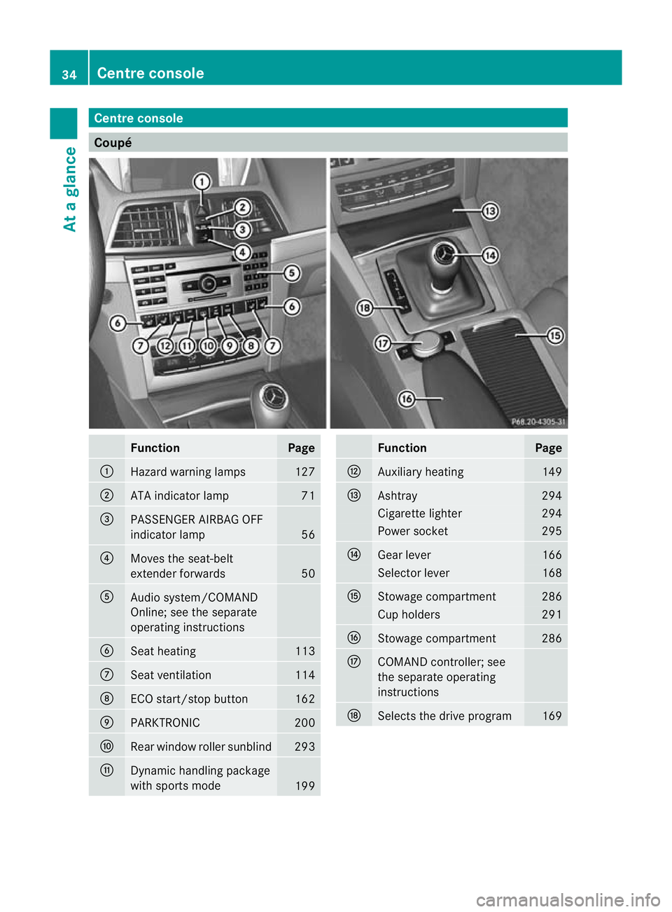
Centre console
Coupé
Function Page
:
Hazard warning lamps 127
;
ATA indicator lamp 71
=
PASSENGER AIRBAG OFF
indicator lamp
56
?
Moves the seat-belt
extender forwards
50
A
Audio system/COMAND
Online; see the separate
operating instructions
B
Seat heating 113
C
Seat ventilation 114
D
ECO start/stop button 162
E
PARKTRONIC 200
F
Rear window roller sunblind 293
G
Dynamic handling package
with sports mode
199 Function Page
H
Auxiliary heating 149
I
Ashtray 294
Cigarette lighter 294
Power socket 295
J
Gear lever 166
Selector lever 168
K
Stowage compartment 286
Cup holders 291
L
Stowage compartment 286
M
COMAND controller; see
the separate operating
instructions N
Selects the drive program 16934
Centre consoleAt a glance
Page 38 of 389
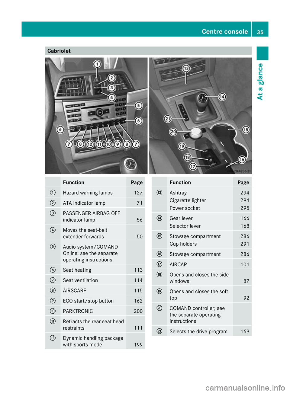
Cabriolet
Function Page
:
Hazard warning lamps 127
;
ATA indicator lamp 71
=
PASSENGER AIRBAG OFF
indicator lamp
56
?
Moves the seat-belt
extender forwards
50
A
Audio system/COMAND
Online; see the separate
operating instructions
B
Seat heating 113
C
Seat ventilation 114
D
AIRSCARF 115
E
ECO start/stop button 162
F
PARKTRONIC 200
G
Retracts the rear seat head
restraints
111
H
Dynamic handling package
with sports mode
199 Function Page
I
Ashtray 294
Cigarette lighter 294
Power socket 295
J
Gear lever 166
Selector lever 168
K
Stowage compartment 286
Cup holders 291
L
Stowage compartment 286
M
AIRCAP 101
N
Opens and closes the side
windows
87
O
Opens and closes the soft
top
92
P
COMAND controller; see
the separate operating
instructions
Q
Selects the drive program 169Centre console
35At a glance
Page 100 of 389
G
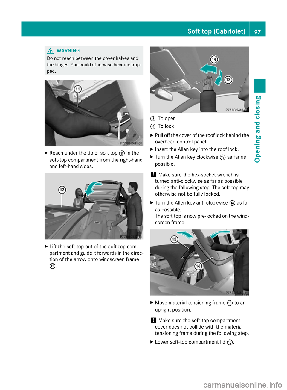
WARNING
Do not reach between the cover halves and
the hinges .You could otherwise become trap-
ped. X
Reach under the tip of soft top Gin the
soft-top compartment from the right-hand
and left-hand sides. X
Lift the soft top out of the soft-top com-
partment and guide it forwards in the direc-
tion of the arrow onto windscreen frame
H. I
To open
J To lock
X Pull off the cover of the roof lock behind the
overhead control panel.
X Insert the Allen key into the roof lock.
X Turn the Allen key clockwise Ias far as
possible.
! Make sure the hex-socket wrench is
turned anti-clockwise as far as possible
during the following step. The soft top may
otherwise not be fully locked.
X Turn the Allen key anti-clockwise Jas far
as possible.
The soft top is now pre-locked on the wind-
screen frame. X
Move material tensioning frame Kto an
upright position.
! Make sure the soft-top compartment
cover does not collide with the material
tensioning frame during the following step.
X Lower soft-top compartment lid L. Soft top (Cabriolet)
97Opening and closing Z
Page 226 of 389

X
Pull the ball coupling in the direction of the
arrow until it engages in a vertical position.
Indicator lamp =goes out. The power
socket folds down automatically.
The multifunction display shows the
Trailer hitch Check lock mech. dis-
play message until the ball coupling is
engaged.
X Remove the protective covering from the
ball coupling and store it in a safe place.
X Make sure that the ball of the ball coupling
is clean and greased. Coupling up a trailer
G
WARNING
If you uncouple a trailer with an engaged over-
run brake, you could trap your hand between
the vehicle and the trailer drawbar. This poses
a risk of injury.
Do not uncouple a trailer with an engaged
overrun brake.
X Make sure that the transmission is in posi-
tion P.
X Apply the parking brake.
X Position the trailer level behind the vehicle.
X Couple up the trailer.
X Establish the electrical connection
between the vehicle and the trailer.
X Check that the trailer lighting system is
working. Uncoupling
atrailer G
WARNING
If you uncouple a trailer with an engaged over-
ru nb rake, you could trap yourh and between
the vehicle and the trailer drawbar .This poses
a risk of injury.
Do not uncouple a trailer with an engaged
overrun brake. G
WARNING
Vehicles with level control:
If you disconnectt he trailer cable, the vehicle
is lowered. This can cause you or others to
become trapped between the vehicle body
and tyres, or underneath the vehicle. This
poses a risk of injury.
Make sure that no-one is in the immediate
vicinity of the wheel arch or underneath the
vehicle when disconnecting the trailer cable.
! Do not disconnect a trailer with an
engaged overrun brake. Otherwise, your
vehicle could be damaged by the rebound-
ing of the overrun brake.
X Make sure that the transmission is in posi-
tion P.
X Apply the parking brake.
X Secure the trailer against rolling away.
X Remove the trailer cable and decouple the
trailer. Folding in the ball coupling
G
WARNING
If you release the ball coupling or it does not
engage correctly when folding in, it will swing
out. Within pivoting range of the ball coupling,
there is an increased risk of an accident and
injury.
Only release the ball coupling if the pivoting
range is unobstructed. Always make sure that
the ball coupling engages when folding in. Towing
atrailer
223Driving an d parking Z
Page 227 of 389
X
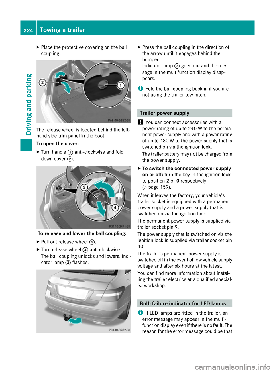
Place the protective covering on the ball
coupling. The release wheel is located behind the left-
hand side trim panel in the boot.
To open the cover:
X
Turn handle :anti-clockwise and fold
down cover ;. To release and lower the ball coupling:
X Pull out release wheel ?.
X Turn release wheel ?anti-clockwise.
The ball coupling unlocks and lowers. Indi-
cator lamp =flashes. X
Press the ball coupling in the direction of
the arrow until it engages behind the
bumper.
Indicator lamp =goes out and the mes-
sage in the multifunction display disap-
pears.
i Fold the ball coupling back in if you are
not using the trailer tow hitch. Trailer power supply
! You can connect accessories with a
power rating of up to 240 W to the perma-
nent power supply and with a power rating
of up to 180 W to the power supply that is
switched on via the ignition lock.
The trailer battery may not be charged from
the power supply.
X To switch the connected power supply
on or off: turn the key in the ignition lock
to position 2or 0respectively
(Y page 159).
When it leaves the factory, your vehicle's
trailer socket is equipped with a permanent
power supply and a power supply that is
switched on via the ignition lock.
The permanen tpower supply is supplied via
trailer socket pin 9.
The power supply that is switched on via the
ignition lock is supplied via trailer socket pin
10.
The trailer's permanent power supply is
switched off in the event of low vehicle supply
voltage and after six hours at the latest.
You can find more information about instal-
ling the trailer electric sataqualified special-
ist workshop. Bulb failure indicator for LED lamps
i If LED lamps are fitted in the trailer, an
error message may appear in the multi-
function display even if there is no fault. The
reason for the error message could be that 224
Towing
atrailerDriving an d parking
Page 228 of 389
the current has fallen below the minimum
of 50 mA.
To ensure reliable operatio nofthe bulb failure
indicator, each LED chain in the trailer lighting
must be guaranteed a minimum current of
50 mA. Trailer with 7-pin connector
General notes Trailers with 7-pin connector:
you can
make a connection to the 13-pin connector
on the ball coupling using an adapter plug or,
if necessary, an adapter cable. Both can be
obtained in a qualified specialist workshop.
Fitting the adapter !
Make sure that there is sufficient cable
play so that the cable cannot become
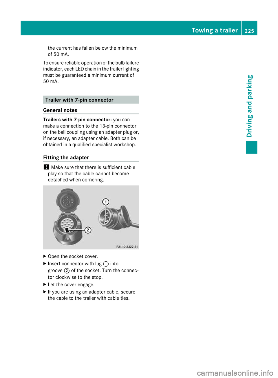
detached when cornering. X
Open the socket cover.
X Insert connector with lug :into
groove ;of the socket. Turn the connec-
tor clockwise to the stop.
X Let the cover engage.
X If you are using an adapter cable, secure
the cable to the trailer with cable ties. Towing
atrailer
225Driving an d parking Z