2012 MERCEDES-BENZ E-CLASS COUPE door lock
[x] Cancel search: door lockPage 278 of 389
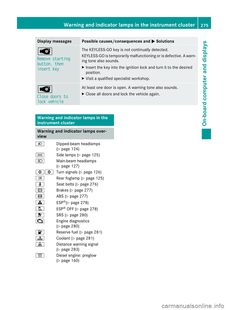
Display messages Possible causes/consequences and
M Solutions
Â
Remove starting
button, then
insert key The KEYLESS-GO key is no
tcontinually detected.
KEYLESS-GO is temporarily malfunctioning or is defective. Awarn-
ing tone also sounds.
X Insert the key into the ignition lock and turn it to the desired
position.
X Visi taqualified specialist workshop. Â
Close doors to
lock vehicle At least one door is open.
Awarning tone also sounds.
X Close all doors and loc kthe vehicle again. Warning and indicator lamps in the
instrument cluster Warning and indicator lamps over-
view
L Dipped-beam headlamps
(Ypage 124)
T Side lamps (Y page 125)
K Main-beam headlamps
(Ypage 127)
#! Turn signals (Y page 126)
R Rear foglamp (Y page 125)
ü Seat belts (Y page 276)
J Brakes (Ypage 277)
! ABS (Ypage 277)
ä ESP®
(Y page 278)
å ESP®
OFF (Y page 278)
6 SRS (Ypage 280)
; Engine diagnostics
(Ypage 280)
8 Reserve fuel (Y page 281)
? Coolant (Ypage 281)
· Distance warning signal
(Ypage 283)
% Diesel engine: preglow
(Ypage 160) Warning and indicator lamps in the instrument cluster
275On-board computer and displays Z
Page 300 of 389
tions. However, the charging function and
aerial functio nare not available.
Operating the mobile phone You can operate the telephone using the
6 and~ buttons on the multifunction
steering wheel. You can operate other mobile
phone functions via the on-board computer
(Y page 238).
When you remove the key from the ignition
lock, the mobile phone stays switched on.
However, you can no longer use the hands-
free system.
If you have an active call and would like to
take the key out of the ignition lock, first
remove the mobile phone from the bracket.
i When using a bracket connected to the
mobile phone via Bluetooth ®
and you wish
to proceed with a call:
Switch to private mode before removing
the key from the ignitio nlock. Otherwise, it
may take up to 20 seconds, before the
mobile phone separates from the system.
Only then can the telephone call continue.
Information on the necessary steps for set-
ting up "private mode" can be found in the
separate mobile phone operating instruc-
tions.
i Not all mobile phones support "private
mode".
Mobile telephone bracket in the stow-
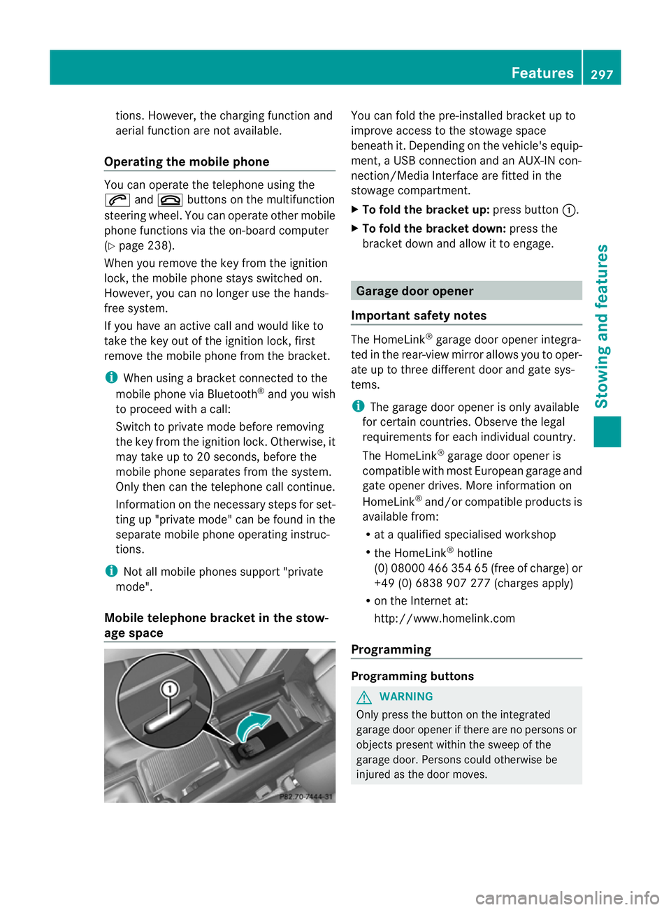
age space You can fold the pre-installed bracket up to
improve access to the stowage space
beneath it. Depending on the vehicle's equip-
ment, a USB connection and an AUX-IN con-
nection/Media Interface are fitted in the
stowage compartment.
X
To fold the bracket up: press button:.
X To fold the bracket down: press the
bracket down and allow it to engage. Garage door opener
Important safety notes The HomeLink
®
garage door opener integra-
ted in the rear-view mirror allows you to oper-
ate up to three different door and gate sys-
tems.
i The garage door opener is only available
for certain countries. Observe the legal
requirements for each individual country.
The HomeLink ®
garage door opener is
compatible with most European garage and
gate opener drives. More information on
HomeLink ®
and/or compatible products is
available from:
R at a qualified specialised workshop
R the HomeLink ®
hotline
(0) 08000 466 354 65 (free of charge) or
+49 (0) 6838 907 277 (charges apply)
R on the Internet at:
http://www.homelink.com
Programming Programming buttons
G
WARNING
Only press the button on the integrated
garage door opener if there are no persons or
objects present within the sweep of the
garage door. Persons could otherwise be
injured as the door moves. Features
297Stowing and features Z
Page 301 of 389
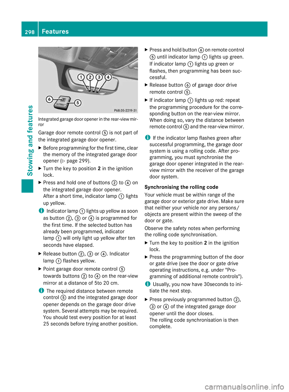
Integrated garage door opener in the rear-view mir-
ror
Garage door remote control
Ais not part of
the integrated garage door opener.
X Before programming for the first time, clear
the memory of the integrated garage door
opener (Y page 299).
X Turn the key to position 2in the ignition
lock.
X Press and hold one of buttons ;to? on
the integrated garage door opener.
After a short time, indicator lamp :lights
up yellow.
i Indicator lamp :lights up yellow as soon
as button ;,=or? is programmed for
the first time. If the selected button has
already been programmed, indicator
lamp :will only lightu p yellow after ten
seconds have elapsed.
X Release button ;,=or?. Indicator
lamp :flashes yellow.
X Point garage door remote control A
towards buttons ;to? on the rear-view
mirror at a distance of 5to 20 cm.
i The required distance between remote
control Aand the integrated garage door
opener depends on the garage door drive
system. Several attempts may be required.
You should test every position for at least
25 seconds before trying another position. X
Press and hold button Bon remot econtrol
A until indicator lamp :lights up green.
If indicator lamp :lights up green or
flashes, then programming has been suc-
cessful.
X Release button Bof garage door drive
remote control A.
X If indicator lamp :lights up red: repeat
the programming procedure for the corre-
sponding button on the rear-view mirror.
When doing so, vary the distance between
remote control Aand the rear-view mirror.
i If the indicator lamp flashes green after
successful programming, the garage door
system is using a rolling code. After pro-
gramming, you must synchronise the
garage door opener integrated in the rear-
view mirror with the receiver of the garage
door system.
Synchronising the rolling code
Your vehicle must be within range of the
garage door or exterior gate drive. Make sure
that neither your vehicle nor any persons/
objects are present within the sweep of the
door or gate.
Observe the safety notes when performing
the rolling code synchronisation.
X Turn the key to position 2in the ignition
lock.
X Press the programming button of the door
or gate drive (see the door or gate drive
operating instructions, e.g. under "Pro-
gramming of additional remote controls").
i Usually, you now have 30seconds to ini-
tiate the next step.
X Press previously programmed button ;,
= or? of the integrated garage door
opener until the door closes.
The rolling code synchronisation is then
complete. 298
FeaturesStowing and features
Page 302 of 389
Problems when programming
If you have problems when programming the
integrated garage door opener, please note
the following:
R Check the transmitter frequency of garage
door drive remote control A.This can usu-
ally be found on the back of the remote
control.
R Replace the batteries in garage door
remote control A.This increases the like-
lihood that garage door remote control A
will transmit a strong and precise signal to
the integrated garage door opener in the
rear-view mirror.
R When programming, hold remote control
A at varying distances and angles from the
button which you are programming. Try var-
ious angles at a distance between 5and
30 cm or at the same angle but at varying
distances.
R If there is another remote control for the
same garage door drive, perform the pro-
gramming steps again using this remote
control. Before performing these steps,
make sure that new batteries have been
fitted in garage door drive remote control
A.
R Note that some remote controls transmit
only for a limited period (the indicator lamp
on the remote control goes out). Press but-
ton Bon remote control Aagain before
transmission ends.
R Align the aerial cable of the garage door
opener unit. This can improve signal recep-
tion/transmission.
Opening or closing the garage door Once programmed, the integrated garage
door opener will assume the function of the
garage door system's remote control. Please
also read the operating instructions for the
garage door system. X
Turn the key to position 2in the ignition
lock.
X Press button ;,=or? which you have
programmed to operate the garage door.
Garage door system with a fixed code: indi-
cator lamp :lights up green.
Garage door system with a rolling code:
indicator lamp :flashes green.
i The transmitter will transmit a signal for
as long as the button is pressed. The trans-
mission is halted after a maximum of ten
seconds and indicator lamp :lights up
yellow. Press button ;,=or? again if
necessary.
Clearing the memory X
Turn the key to position 2in the ignition
lock.
X Press buttons ;and ?.
The indicator lamp lights up yellow.
X Press and hold buttons ;and ?until the
indicator lamp turns green.
i Make sure that you clear the memory of
the integrated garage door opener before
selling the vehicle.
Frequencies Europe
Country Radio type approval num-
ber
Frequency range (MHz)
AD (Andorra) 20 July
MHz: 27, 30, 40, 433, 868
AT (Austria) Article 6 of Directive
1999/5/EC R&TTE 18 May
05
MHz: 27, 40, 433, 868
BE (Belgium) Article 6 of Directive
1999/5/EC R&TTE 18 May
05
MHz: 27, 40, 433, 868 Features
299Stowing and features Z
Page 327 of 389
The vehicle tool kit contains:
R
Cabriolet: straps for emergency release of
the soft top
R Foldable wheel chock
R Fuse allocation chart
R Jack
R Centring pin
R One pair of gloves
R wheel wrench
R Towing eye Flat tyre
Preparing the vehicle
Information on changing a wheel/fitting
(Y page 346).
Vehicle preparation is not necessary on vehi-
cles with MOExtended tyres.
Your vehicle may be equipped with:
R MOExtended tyres (tyres with run-flat char-
acteristics) (Y page 324)
R a TIREFIT kit (Y page 325)
R an emergency spare wheel (only for certain
countries) (Y page 363)
X Stop the vehicle as far away as possible
from traffic on solid, non-slippery and level
ground.
X Switch on the hazard warning lamps.
X Apply the parking brake.
X Bring the frontw heels into the straight-
ahead position.
X Shift the transmission to position P.
X Switch off the engine.
X Vehicles without KEYLESS-GO: remove
the key from the ignition lock.
X Vehicles with KEYLESS-GO: open the
driver's door.
The on-board electronics have status 0,
which is the same as the key having been
removed. X
Vehicles with KEYLESS-GO: remove the
Start/Stop button from the ignition lock
(Y page 159).
X All occupants must get out of the vehicle.
Make sure that they are not endangered as
they do so.
X Make sure that no one is near the danger
area while a wheel is being changed. Any-
one who is not directly assisting in the
wheel change should, for example, stand
behind the barrier.
X Get out of the vehicle. Pay attention to traf-
fic conditions when doing so.
X Close the driver's door.
X Place the warning triangle a suitable dis-
tance away (Y page 322). Observe legal
requirements. MOExtended tyres (tyres with run-flat
characteristics)
G
WARNING
When driving in emergency mode, the driving
characteristics deteriorate, e.g. when corner-
ing, accelerating quickly and when braking.
There is a risk of accident.
Do not exceed the stated maximum speed.
Avoid abrupt steering and driving manoeu-
vres, and driving over obstacles (kerbs, pot-
holes, off-road). This applies in particular to a
laden vehicle.
Stop driving in emergency mode if:
R you hear banging noises.
R the vehicle starts to shake.
R you see smoke and smell rubber.
R ESP ®
is intervening constantly.
R there are tears in the sidewalls of the tyre.
After driving in emergency mode, have the
wheel rims checked at a qualified specialist
workshop with regard to their further use. The
faulty tyre must be replaced.
With MOExtended tyres (tyres with run-flat
characteristics), you can continue to drive 324
Flat tyreBreakdown assistance
Page 350 of 389
X
Vehicles withou tKEYLESS-GO: remove
the key from the ignition lock.
X Vehicles with KEYLESS-GO: open the
driver's door.
The on-board electronics have status 0,
which is the same as the key having been
removed.
X Vehicles with KEYLESS-GO: remove the
Start/Stop button from the ignition lock
(Y page 159).
X If included in the vehicle equipment,
remove the tyre-change tool kit from the
vehicle.
X Secure the vehicle to prevent it from rolling
away.
i Apart from certain country-specific varia-
tions, the vehicles are no tequipped with a
tyre-change tool kit .Some tools for chang-
ing a wheel are specific to the vehicle. For
more information on which tools are
required to perform a wheel change on your
vehicle, consult a qualified specialist work-
shop.
Necessary wheel-changing tools can
include, for example:
R jack
R wheel chock
R wheel wrench
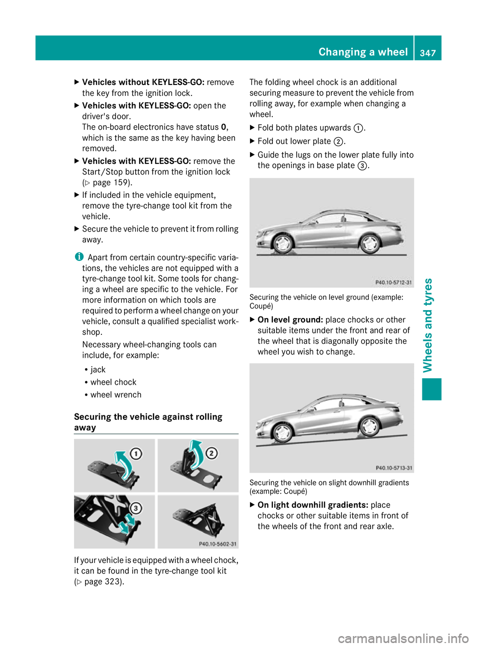
Securing the vehicle against rolling
away If your vehicle is equipped with a wheel chock,
it can be found in the tyre-change tool kit
(Y page 323). The folding wheel chock is an additional
securing measure to prevent the vehicle from
rolling away, for example when changing a
wheel.
X
Fold both plates upwards :.
X Fold out lower plate ;.
X Guide the lugs on the lower plate fully into
the openings in base plate =. Securing the vehicle on level ground (example:
Coupé)
X
On level ground: place chocks or other
suitable items under the front and rear of
the wheel that is diagonally opposite the
wheel you wish to change. Securing the vehicle on slight downhill gradients
(example: Coupé)
X
On light downhill gradients: place
chocks or other suitable items in front of
the wheels of the front and rear axle. Changing
awheel
347Wheels and tyres Z
Page 351 of 389
Raising the vehicle
G
WARNING
If you do not position the jack correctly at the
appropriate jacking point of the vehicle, the
jack could tip ove rwith the vehicle raised.
There is a risk of injury.
Only position the jac katthe appropriate jack-
ing point of the vehicle. The base of the jack
must be positioned vertically, directly under
the jacking point of the vehicle.
The following must be observed when raising
the vehicle:
R to raise the vehicle, only use the vehicle-
specific jack that has been tested and
approved by Mercedes-Benz. If the jack is
used incorrectly, it could tip over while the
vehicle is raised.
R the jack is designed only to raise and hold
the vehicle for a short time while a wheel
is being changed. It is not suited for per-
forming maintenance work under the vehi-
cle.
R avoid changing the wheel on uphill and
downhill slopes.
R before raising the vehicle, secure it from
rolling away by applying the parking brake
and inserting wheel chocks. Never disen-
gage the parking brake while the vehicle is
raised.
R the jack must be placed on a firm, flat and
non-slip surface. On a loose surface, a
large, load-bearing underlay must be used.
On a slippery surface, a non-slip underlay
must be used, e.g. rubber mats.
R do not use wooden blocks or similar
objects as a jack underlay.O therwise, the
jack will not be able to achieve its load-
bearing capacity due to the restricted
height.
R make sure tha tthe distance between the
underside of the tyres and the ground does
not exceed 3 cm.
R never place your hands or feet under the
raised vehicle. R
never lie under the raised vehicle.
R never start the engine when the vehicle is
raised.
R never open or close a door or the boot lid
when the vehicle is raised.
R make sure that no persons are present in
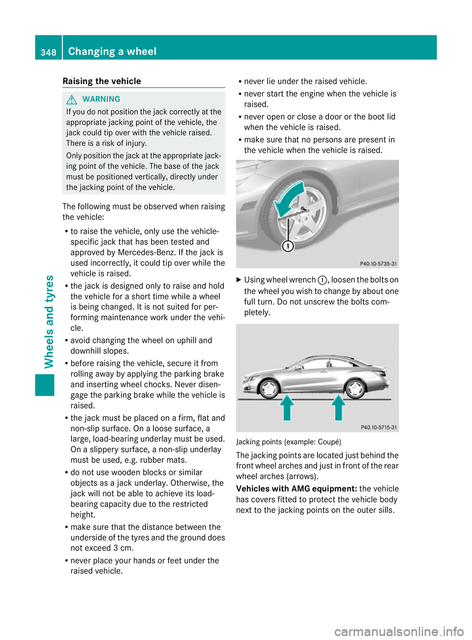
the vehicle when the vehicle is raised. X
Using wheel wrench :, loosen the bolts on
the wheel you wish to change by about one
full turn. Do not unscrew the bolts com-
pletely. Jacking points (example: Coupé)
The jacking points are located just behind the
front wheel arches and just in front of the rear
wheel arches (arrows).
Vehicles with AMG equipment: the vehicle
has covers fitted to protect the vehicle body
next to the jacking points on the outer sills. 348
Changing
awheelWheels and tyres