2012 LINCOLN MKT ESP
[x] Cancel search: ESPPage 123 of 437

WARNING:Always pay close attention to changing road
conditions, especially when using Adaptive Cruise Control.
Adaptive Cruise Control cannot replace attentive driving. Failing to
follow any of the warnings below or failing to pay attention to the road
may result in a collision, serious injury or death.
WARNING:Adaptive cruise control is not a collision warning or
avoidance system. Additionally, adaptive cruise control will not
detect:
•Stationary or slow moving vehicles below 6 mph (10 km/h).
•Pedestrians or objects in the roadway.
•Oncoming vehicles in the same lane.
WARNING:Do not use the adaptive cruise control when
entering or leaving a highway, in heavy traffic or on roads that
are winding, slippery or unpaved.
WARNING:Do not use in poor visibility, specifically fog, rain,
spray or snow.
Setting adaptive cruise control
Note:It is the driver’s responsibility to stay alert, drive safely and be in
control of the vehicle at all times.
The controls for using your cruise
control are located on the steering
wheel.
1. Press and release the ON control.
The message center will display
CRUISE ON RADAR READY.
2. Accelerate to the desired speed.
Driver Controls
123
2012 MKT(mkt)
Owners Guide, 1st Printing
USA(fus)
Page 125 of 437

If the ACC system predicts that its
maximum braking level will not be
sufficient, an audible warning will
sound while the ACC continues to
brake. This is accompanied by the
heads-up display; a red warning bar
illuminating on the windshield. The driver should takeimmediateaction.
Note:The brakes may emit a sound when they are being modulated by
the adaptive cruise control system.
WARNING:Adaptive cruise control only warns of vehicles
detected by the radar sensor. In some cases there may be no
warning or the warning may be delayed. The driver should always
apply the brakes when necessary. Failing to do so may result in a
collision, serious injury or death.
Setting the gap distance
The distance between your vehicle
and the vehicle in front of you can
be decreased or increased by
pressing<--->control. GAP <--->
will be displayed in the message
center. Three gap distance settings
are available:
Message
center displayFollowing
distanceFollowing
distance at
60 mph
(100 km/h)Dynamic
behavior
GAP <-> 1 second 29 yards (28 m) Sporty
GAP <---> 1.5 seconds 44 yards (42 m) Normal
GAP <-----> 2.3 seconds 66 yards (64 m) Comfort
Each time the vehicle is restarted, the last chosen gap will be
automatically selected.
Note:It is the driver’s responsibility to select a gap appropriate to the
driving conditions.
Driver Controls
125
2012 MKT(mkt)
Owners Guide, 1st Printing
USA(fus)
Page 130 of 437

Blocked sensor
If a message regarding a blocked
sensor is displayed, the radar signals
from the sensor have been
obstructed. The sensor is located
behind a fascia cover near the driver
side of the lower grille. When the
radar signals are obstructed, a
vehicle ahead cannot be detected
and the ACC will not function. The
following table lists possible causes
and actions for this message being displayed.
Cause Action
The surface of the radar in the
grille is dirty or obstructed in
some wayClean the grille surface in front of
the radar or remove the object
causing the obstruction
The surface of the radar in the
grille is clean but the message
remains in the displayWait a short time. It may take
several minutes for the radar to
detect that it is no longer
obstructed
Heavy rain or snow is interfering
with the radar signalsDo not use ACC in these
conditions because it may not
detect, warn, or respond to
potential collisions.
Swirling water, or snow or ice on
the surface of the road may
interfere with the radar signalsDo not use ACC in these
conditions because it may not
detect, warn, or respond to
potential collisions.
Desert / remote area with no other
vehicles and no roadside objectsWait a short time.
Due to the nature of radar technology, it is possible to get a blockage
warning and not be blocked. This can happen, for example, when driving
in sparse rural or desert environments. A false blocked condition will
either self clear or clear after a key cycle.
Driver Controls
130
2012 MKT(mkt)
Owners Guide, 1st Printing
USA(fus)
Page 140 of 437

cycle and the liftgate is 6-10 inches (15–24 cm) from being latched, the
liftgate may reverse to the full open position. Verify that the gate is
closed before operating or moving the vehicle, especially in an enclosure,
like a garage or a parking structure. The liftgate or it components could
be damaged in an enclosure, if the liftgate is open.
When power operating the liftgate at temperatures below 32°F (0°C), the
liftgate may stop about 5 inches (12.7 cm) from the full open position.
The liftgate can be fully opened by pushing it upward to the maximum
open position.
The power liftgate feature can be enabled or disabled using the message
center controls. With the setting turned off, power operation is disabled
from the liftgate control button and from the rear cargo area button. The
transmitter and instrument panel switch will still continue to operate the
liftgate regardless of the position state of the message center. Refer to
Message centerin theInstrument Clusterchapter.
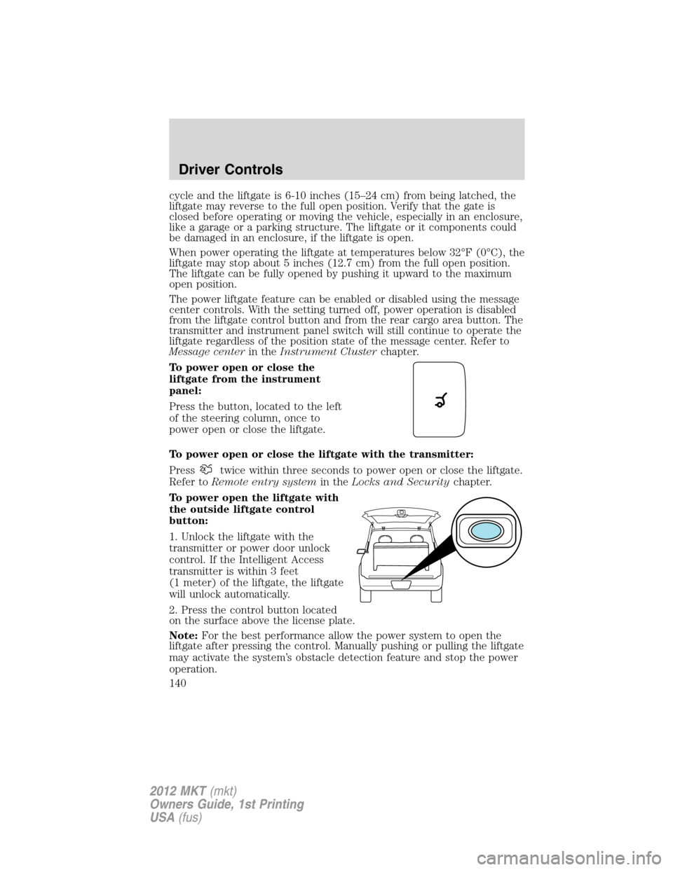
To power open or close the
liftgate from the instrument
panel:
Press the button, located to the left
of the steering column, once to
power open or close the liftgate.
To power open or close the liftgate with the transmitter:
Press
twice within three seconds to power open or close the liftgate.
Refer toRemote entry systemin theLocks and Securitychapter.
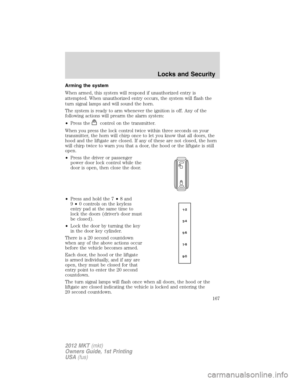
To power open the liftgate with
the outside liftgate control
button:
1. Unlock the liftgate with the
transmitter or power door unlock
control. If the Intelligent Access
transmitter is within 3 feet
(1 meter) of the liftgate, the liftgate
will unlock automatically.
2. Press the control button located
on the surface above the license plate.
Note:For the best performance allow the power system to open the
liftgate after pressing the control. Manually pushing or pulling the liftgate
may activate the system’s obstacle detection feature and stop the power
operation.
Driver Controls
140
2012 MKT(mkt)
Owners Guide, 1st Printing
USA(fus)
Page 155 of 437

REMOTE ENTRY SYSTEM
The intelligent access keys (IA key) comply with part 15 of the FCC
rules and with RSS-210 of Industry Canada. Operation is subject to the
following two conditions: (1) This device may not cause harmful
interference, and (2) This device must accept any interference received,
including interference that may cause undesired operation.
Changes or modifications not expressly approved by the party
responsible for compliance could void the user’s authority to
operate the equipment.
The typical operating range for your transmitter is approximately 33 feet
(10 meters). A decrease in operating range could be caused by:
•weather conditions,
•nearby radio towers,
•structures around the vehicle, or
•other vehicles parked next to your vehicle.
The transmitter allows you to:
•remotely unlock the vehicle doors
.
•remotely lock all the vehicle doors
.
•remotely open the power liftgate
.
•activate the personal alarm
.
•arm and disarm the perimeter anti-theft system.
•operate the illuminated entry feature.
•activate the global opening windows feature.
Refer toIntelligent Accessin this section for more features.
The remote entry lock/unlock feature operates in any ignition position
except while the vehicle is in the start position. The panic feature
operates with the ignition off.
If there are problems with the remote entry system, make sure to take
ALL intelligent access keyswith you to the authorized dealer in order
to aid in troubleshooting the problem.
Locks and Security
155
2012 MKT(mkt)
Owners Guide, 1st Printing
USA(fus)
Page 167 of 437

Arming the system
When armed, this system will respond if unauthorized entry is
attempted. When unauthorized entry occurs, the system will flash the
turn signal lamps and will sound the horn.
The system is ready to arm whenever the ignition is off. Any of the
following actions will prearm the alarm system:
•Press the
control on the transmitter.
When you press the lock control twice within three seconds on your
transmitter, the horn will chirp once to let you know that all doors, the
hood and the liftgate are closed. If any of these are not closed, the horn
will chirp twice to warn you that a door, the hood or the liftgate is still
open.
•Press the driver or passenger
power door lock control while the
door is open, then close the door.
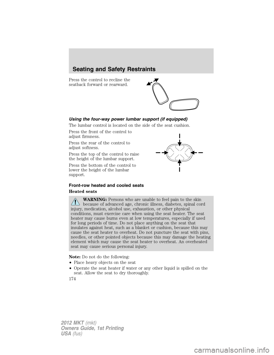
•Press and hold the 7•8 and
9•0 controls on the keyless
entry pad at the same time to
lock the doors (driver’s door must
be closed).
•Lock the door by turning the key
in the door key cylinder.
There is a 20 second countdown
when any of the above actions occur
before the vehicle becomes armed.
Each door, the hood or the liftgate
is armed individually, and if any are
open, they must be closed for that
entry point to enter the 20 second
countdown.
The turn signal lamps will flash once when all doors, the hood or the
liftgate are closed indicating the vehicle is locked and entering the
20 second countdown.
Locks and Security
167
2012 MKT(mkt)
Owners Guide, 1st Printing
USA(fus)
Page 174 of 437

Press the control to recline the
seatback forward or rearward.
Using the four-way power lumbar support (if equipped)
The lumbar control is located on the side of the seat cushion.
Press the front of the control to
adjust firmness.
Press the rear of the control to
adjust softness.
Press the top of the control to raise
the height of the lumbar support.
Press the bottom of the control to
lower the height of the lumbar
support.
Front-row heated and cooled seats
Heated seats
WARNING:Persons who are unable to feel pain to the skin
because of advanced age, chronic illness, diabetes, spinal cord
injury, medication, alcohol use, exhaustion, or other physical
conditions, must exercise care when using the seat heater. The seat
heater may cause burns even at low temperatures, especially if used
for long periods of time. Do not place anything on the seat that
insulates against heat, such as a blanket or cushion, because this may
cause the seat heater to overheat. Do not puncture the seat with pins,
needles, or other pointed objects because this may damage the heating
element which may cause the seat heater to overheat. An overheated
seat may cause serious personal injury.
Note:Do not do the following:
•Place heavy objects on the seat
•Operate the seat heater if water or any other liquid is spilled on the
seat. Allow the seat to dry thoroughly.
Seating and Safety Restraints
174
2012 MKT(mkt)
Owners Guide, 1st Printing
USA(fus)
Page 190 of 437

Front safety belt usage sensors
The front safety belt usage sensors detect whether or not the driver and
front outboard passenger safety belts are fastened. This information
allows your Personal Safety System to tailor the airbag deployment and
safety belt pretensioner activation depending upon safety belt usage.
Front safety belt pretensioners
The safety belt pretensioners at the front outboard seating positions are
designed to tighten the safety belts firmly against the occupant’s body
during frontal collisions, and in side collisions and rollovers. This helps
increase the effectiveness of the safety belts. In frontal collisions, the
safety belt pretensioners can be activated alone or, if the collision is of
sufficient severity, together with the front airbags.
Front safety belt energy management retractors
The front outboard safety belt energy management retractors allow
webbing to be pulled out of the retractor in a gradual and controlled
manner in response to the occupant’s forward momentum. This helps
reduce the risk of force-related injuries to the occupant’s chest by
limiting the load on the occupant. Refer toEnergy management
feature- front outboardsection in this chapter.
Determining if the Personal Safety System is operational
The Personal Safety System uses a warning light in the instrument
cluster or a back-up tone to indicate the condition of the system. Refer
to theWarning lights and chimessection in theInstrument Cluster
chapter. Routine maintenance of the Personal Safety System is not
required.
The Restraints Control Module (RCM) monitors its own internal circuits
and the circuits for the airbag supplemental restraints, crash sensor(s),
safety belt pretensioners, front safety belt buckle sensors, driver seat
position sensor, and front passenger sensing system. In addition, the
RCM also monitors the restraints warning light in the instrument cluster.
A difficulty with the system is indicated by one or more of the following.
•The warning light will either flash or stay lit.
•The warning light will not illuminate immediately after ignition is
turned on.
•A series of five beeps will be heard. The tone pattern will repeat
periodically until the problem and warning light are repaired.
If any of these things happen, even intermittently, have the Personal
Safety System serviced at an authorized dealer immediately. Unless
serviced, the system may not function properly in the event of a
collision.
Seating and Safety Restraints
190
2012 MKT(mkt)
Owners Guide, 1st Printing
USA(fus)