2012 KIA PICANTO display
[x] Cancel search: displayPage 259 of 840

515
Driving your vehicle
ISG system deactivation
If you wish to deactivate the ISG sys-tem, press the ISG OFF button. The
light on the ISG OFF button will illumi-
nate and a message “Auto Stop Off ” will
appear on the LCD display.
If you press the ISG OFF button again, the system will be activated and the
light on the ISG OFF button will turn off. ISG system malfunction
The system may not operate when:
The ISG related sensors or system error
occurs.
The following will happen:
The yellow AUTO STOP ( ) indica-
tor on the instrument cluster will stay
on after blinking for 5 seconds.
✽✽ NOTICE
If the ISG OFF button light is not turned off by pressing the ISG OFF
button again or if the ISG system con-
tinuously does not work correctly,
please contact an authorized KIA
dealer as soon as possible.
When the ISG OFF button light comes
on, it may stop illuminating after driv-
ing your vehicle at approximately 80
km/h for a maximum of two hours
and setting the fan speed control
below the 2nd position. If the ISG
OFF button light continues to illumi-
nate in spite of the procedure, please
contact an authorized KIA dealer as
soon as possible.
OTA052028L
OTA050018L
OTA052027L
Page 272 of 840

Driving your vehicle
28
5
For smooth operation, depress the brake
pedal when shifting from N (Neutral) to aforward or reverse gear.Transaxle ranges
The indicator in the instrument cluster
displays the shift lever position when the
ignition switch is in the ON position.
P (Park)
Always come to a complete stop before
shifting into P (Park). This position locks
the transaxle and prevents the drivewheels from rotating.
WARNING - Automatic
transaxle
Always check the surrounding areas near your vehicle for peo-
ple, especially children, beforeshifting a car into D (Drive) or R
(Reverse).
Before leaving the driver’s seat, always make sure the shift lever
is in the P (Park) position; then
set the parking brake fully and
shut the engine off. Unexpected
and sudden vehicle movementcan occur if these precautions
are not followed in the order iden-tified.
CAUTION
To avoid damage to your
transaxle, do not accelerate the
engine in R (Reverse) or any for-ward gear position with thebrakes on.
When stopped on an incline, do not hold the vehicle stationarywith engine power. Use the serv-ice brake or the parking brake.
Do not shift from N (Neutral) or P (Park) into D (Drive), or R
(Reverse) when the engine isabove idle speed.
WARNING
Shifting into P (Park) while the vehicle is in motion will cause the
drive wheels to lock which will
cause you to lose control of the
vehicle.
Do not use the P (Park) position in place of the parking brake.
Always make sure the shift lever
is latched in the P (Park) position
and set the parking brake fully.
Never leave a child unattended in a vehicle.
CAUTION
The transaxle may be damaged if
you shift into P (Park) while the vehicle is in motion.
Page 324 of 840

617
What to do in an emergency
0. Speed restriction label
1. Sealant bottle and label withspeed restriction
2. Filling hose from sealant bottle to wheel 3. Connectors and cable for the
power outlet direct connection
4. Holder for the sealant bottle
5. Compressor
6. On/off switch 7. Pressure gauge for displaying the
tire inflation pressure
8. Button for reducing tire inflation pressure
9. Hose to connect compressor and sealant bottle or compressor and wheel
Connectors, cable and connectionhose are stored in the compressorhousing.
WARNING
Before using the TireMobilityKit,
follow the instructions on the
sealant bottle.
Remove the label with the speed
restriction from the sealant bottle
and apply it to the steering wheel.
Please note the expiry date on the
sealant bottle.
Components of the TireMobilityKit
OAM060015L
Page 380 of 840

Maintenance
48
7
Tire speed ratings
The chart below lists many of the dif-
ferent speed ratings currently being
used for passenger car tires. The
speed rating is part of the tire size
designation on the sidewall of the
tire. This symbol corresponds to that
tire's designed maximum safe oper-ating speed.3. Checking tire life (TIN : Tire
Identification Number)
Any tires that are over 6 years old,
based on the manufacturing date,(including the spare tire) should be
replaced by new ones. You can find
the manufacturing date on the tire
sidewall (possibly on the inside of the
wheel), displaying the DOT Code.
The DOT Code is a series of num-
bers on a tire consisting of numbers
and English letters. The manufactur-
ing date is designated by the last four
digits (characters) of the DOT code.
DOT : XXXX XXXX OOOO
The front part of the DOT means a
plant code number, tire size and
tread pattern and the last four num-
bers indicate week and year manu-
factured.
For example:
DOT XXXX XXXX 1611 represents
that the tire was produced in the 16th
week of 2011.
S 180 km/h (112 mph)
T 190 km/h (118 mph)
H 210 km/h (130 mph) V 240 km/h (149 mph)
Z Above 240 km/h (149 mph)
Maximum Speed
Speed
Rating
Symbol
WARNING - Tire age
Tires degrade over time, even
when they are not being used.
Regardless of the remaining
tread, it is recommended that
tires generally be replaced after
six (6) years of normal service.
Heat caused by hot climates orfrequent high loading condi-
tions can accelerate the aging
process. Failure to follow this
warning can result in sudden
tire failure, which could lead to
a loss of control and an acci-
dent involving serious injury ordeath.
Page 420 of 840

I3
Index
Cargo weight ..................................................................5-63
Central door lock switch ................................................4-17
Changing tires ..................................................................6-9Chains
Tire chains ................................................................5-52
Checking tire inflation pressure ......................................7-42
Child restraint system ....................................................3-28 Lap belt......................................................................3-31
Lap/shoulder belt ......................................................3-30
Child-protector rear door lock ........................................4-18
Climate control system (Automatic) ..............................4-93 Air conditioning ........................................................4-98
Automatic heating and air conditioning....................4-94
Manual heating and air conditioning ........................4-95
Climate control system (Manual) ..................................4-84 Air conditioning ........................................................4-89
Climate control air filter............................................4-91
Heating and air conditioning ....................................4-85
Cigarette lighter ............................................................4-104
Climate control air filter ........................................4-91, 7-33
Clock (Digital) ..............................................................4-107
Clothes hanger ..............................................................4-108
Combined instrument, see instrument cluster ................4-42
Coolant ............................................................................7-24
Cooling fluid, see engine coolant ..................................7-24
Crankcase emission control system ................................7-76
Cup holder ....................................................................4-105
Curtain air bag ................................................................3-52 Dashboard, see instrument cluster ..................................4-42
Daytime running light ....................................................4-70
Defogging (Windshield) ..............................................4-100
Defogging logic (Windshield) ......................................4-102
Defroster (Rear window) ................................................4-83
Defrosting (Windshield) ..............................................4-100
Digital clock..................................................................4-107
Dimensions ......................................................................8-2
Displays, see instrument cluster ....................................4-42
Door locks ......................................................................4-15
Central door lock switch ..........................................4-17
Child-protector rear door lock ..................................4-18
Drink holders, see cup holders ......................................4-99
Driver's air bag ................................................................3-46
Driving at night ..............................................................5-48
Driving in flooded areas ................................................5-50
Driving in the rain ..........................................................5-49D
Page 540 of 840

441
Features of your vehicle
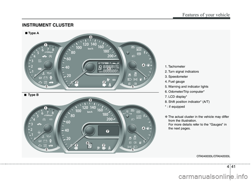
INSTRUMENT CLUSTER
1. Tachometer
2. Turn signal indicators
3. Speedometer
4. Fuel gauge
5. Warning and indicator lights
6. Odometer/Trip computer*
7. LCD display*
8. Shift position indicator* (A/T)
* : if equipped ❈The actual cluster in the vehicle may differ
from the illustration.
For more details refer to the "Gauges" in
the next pages.
OTA040033L/OTA042033L
■■Type A
■■
Type B
Page 541 of 840

Features of your vehicle
42
4
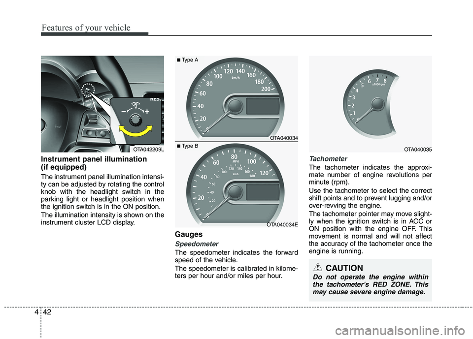
Instrument panel illumination (if equipped)
The instrument panel illumination intensi-
ty can be adjusted by rotating the control
knob with the headlight switch in the
parking light or headlight position when
the ignition switch is in the ON position.
The illumination intensity is shown on the
instrument cluster LCD display.
Gauges
Speedometer
The speedometer indicates the forward
speed of the vehicle.
The speedometer is calibrated in kilome-
ters per hour and/or miles per hour.
Tachometer
The tachometer indicates the approxi-
mate number of engine revolutions per
minute (rpm). Use the tachometer to select the correct
shift points and to prevent lugging and/or
over-revving the engine.
The tachometer pointer may move slight-
ly when the ignition switch is in ACC or
ON position with the engine OFF. This
movement is normal and will not affect
the accuracy of the tachometer once the
engine is running.
OTA040034
OTA040034E
■Type A
■Type BOTA040035
CAUTION
Do not operate the engine within
the tachometer's RED ZONE. This may cause severe engine damage.
OTA042209L
Page 542 of 840

443
Features of your vehicle
Fuel gauge
The fuel gauge indicates the approxi- mate amount of fuel remaining in the fueltank.
The fuel tank capacity is given in sec-
tion 8.The fuel gauge is supplemented by
a low fuel warning light, which will illumi-
nate when the fuel tank is nearly empty.
On inclines or curves, the fuel gauge
pointer may fluctuate or the low fuel
warning light may come on earlier than
usual due to the movement of fuel in thetank.
Trip computer (if equipped)
The trip computer is a microcomputer-
controlled driver information system that
displays information related to driving on
the display when the ignition switch is in
the ON position. All stored driving infor-
mation (except odometer) is reset if the
battery is disconnected.
WARNING - Fuel gauge
Running out of fuel can expose
vehicle occupants to danger.
You must stop and obtain addition-
al fuel as soon as possible after thewarning light comes on or when the
gauge indicator comes close to the
E level.
CAUTION
Avoid driving with a extremely low fuel level. Running out of fuel couldcause the engine to misfire, damag-ing the catalytic converter.OTA040037OTA040036/OTA040036L
■
Type A ■Type B