Page 338 of 558
4WD Lock
Four-Wheel Drive High Range - This range locks the front
driveshaft and rear driveshaft together forcing the front
and rear wheels to rotate at the same speed. Additional
traction for loose or slippery road surfaces only.
4WD Low
Four-Wheel Drive Low Range - This range provides low
speed four-wheel drive. Locks the front driveshaft and
rear driveshaft together forcing the front and rear wheels
to rotate at the same speed. Additional traction and
maximum pulling power for loose or slippery road
surfaces only. Do not exceed 25 mph (40 km/h).
N
Neutral - This range disengages both the front driveshaft
and rear driveshaft from the powertrain. To be used for
flat towing behind another vehicle. Refer to “Recreational
Towing” in “Starting and Operating” for further
information.
Transfer Case Position Indicator Lights
The four-wheel drive indicator lights (4WD and 4 LOW)
are located in the instrument cluster. The NEUTRAL
indicator light is located on the transfer case switch. If
there is no indicator light on or flashing, the transfer case
position is two-wheel drive (2WD). If the indicator light
is on, the desired position (4WD LOCK, 4WD LOW, or
NEUTRAL) has been obtained.
If One Or More Shift Requirements Are Not Met:
•An indicator light will flash.
•The transfer casewill notshift.
NOTE: The “SERV 4WD Warning Light” monitors the
electric shift four-wheel drive system. If this light re-
mains on after engine start up, or it illuminates during
driving, it means that the four-wheel drive system is not
functioning properly and that service is required.
336 STARTING AND OPERATING
Page 345 of 558
NOTE:The “SERV 4WD Warning Light” monitors the
electric shift four-wheel drive system. If this light re-
mains on after engine start up, or it illuminates during
driving, it means that the four-wheel drive system is not
functioning properly and that service is required.
Shifting Procedures
NOTE: If any of the requirements to select a new
transfer case position have not been met, the transfer case
will not shift, the indicator light for the previous position
will remain on, and the newly selected position indicator
light will continue to flash until all the requirements for
the selected position have been met. To retry a shift, move
the transfer case switch back to the original position,
make certain all shift requirements have been met, wait
five seconds, and try the shift again.
2WD To 4WD Auto
Move the transfer case switch to the desired position.
Shifts between 2WD and 4WD Auto can be done with the vehicle stopped or in motion. If the vehicle is stopped,
the ignition switch must be in the ON position with the
engine either OFF or RUNNING. This shift cannot be
completed if the ignition switch is in the ACC position.
2WD Or 4WD Auto To 4WD Low
When shifting into or out of 4WD LOW, some gear noise
may be heard. This noise is normal and is not detrimental
to the vehicle or its occupants.
Shifting can be performed with the vehicle rolling 2 to
3 mph (3 to 5 km/h) using the “Preferred Procedure” or
completely stopped using the “Alternate Procedure.”
Preferred Procedure
1. With the engine RUNNING, slow the vehicle speed to
2 to 3 mph (3 to 5 km/h).
2. Shift the transmission into NEUTRAL.
5
STARTING AND OPERATING 343
Page 350 of 558
turning the front wheels slowly left and right. This may
provide a fresh “bite” into the surface and will usually
provide traction to complete the climb.
Traction Downhill
Shift the transmission into a low gear and the transfer
case to 4WD LOW range. Let the vehicle go slowly down
the hill with all four wheels turning against engine
compression drag. This will permit you to control the
vehicle speed and direction.
When descending mountains or hills, repeated braking
can cause brake fade with loss of braking control. Avoid
repeated heavy braking by downshifting the transmis-
sion whenever possible.
After Driving Off-Road
Off-road operation puts more stress on your vehicle than
does most on-road driving. After going off-road, it isalways a good idea to check for damage. That way you
can get any problems taken care of right away and have
your vehicle ready when you need it.
•Completely inspect the underbody of your vehicle.
Check tires, body structure, steering, suspension, and
exhaust system for damage.
•Inspect the radiator for mud and debris and clean as
required.
•Check threaded fasteners for looseness, particularly on
the chassis, drivetrain components, steering, and sus-
pension. Retighten them, if required, and torque to the
values specified in the Service Manual.
•Check for accumulations of plants or brush. These
things could be a fire hazard. They might hide damage
to fuel lines, brake hoses, axle pinion seals, and
propeller shafts.
348 STARTING AND OPERATING
Page 352 of 558
system. This noise should be considered normal, and it
does not in any way damage the steering system.
WARNING!
Continued operation with reduced power steering
assist could pose a safety risk to yourself and others.
Service should be obtained as soon as possible.
CAUTION!
Prolonged operation of the steering system at the end
of the steering wheel travel will increase the steering
fluid temperature and it should be avoided when
possible. Damage to the power steering pump may
occur.
Power Steering Fluid Check
Checking the power steering fluid level at a defined
service interval is not required. The fluid should only bechecked if a leak is suspected, abnormal noises are
apparent, and/or the system is not functioning as antici-
pated. Coordinate inspection efforts through an autho-
rized dealer.
CAUTION!
Do not use chemical flushes in your power steering
system as the chemicals can damage your power
steering components. Such damage is not covered by
the New Vehicle Limited Warranty.
WARNING!
Fluid level should be checked on a level surface and
with the engine off to prevent injury from moving
parts and to ensure accurate fluid level reading. Do
not overfill. Use only manufacturer’s recommended
power steering fluid.
350 STARTING AND OPERATING
Page 355 of 558
WARNING! (Continued)
•Be sure the parking brake is fully disengaged
before driving; failure to do so can lead to brake
failure and a collision.
•Always fully apply the parking brake when leav-
ing your vehicle or it may roll and cause damage or
injury. Also, be certain to leave the transmission in
PARK. Failure to do so may cause the vehicle to
roll and cause damage or injury.
CAUTION!
If the “Brake Warning Light” remains on with the
parking brake released, a brake system malfunction
is indicated. Have the brake system serviced by an
authorized dealer immediately.
ANTI-LOCK BRAKE SYSTEM
The Anti-Lock Brake System (ABS) is designed to aid the
driver in maintaining vehicle control under adverse
braking conditions. The system operates with a separate
computer to modulate hydraulic pressure, to prevent
wheel lock-up and help avoid skidding on slippery
surfaces.
All vehicle wheels and tires must be the same size and
type, and tires must be properly inflated, to produce
accurate signals for the computer.
WARNING!
Significant over or under-inflation of tires or mixing
sizes of tires or wheels on the vehicle can lead to loss
of braking effectiveness.
5
STARTING AND OPERATING 353
Page 370 of 558
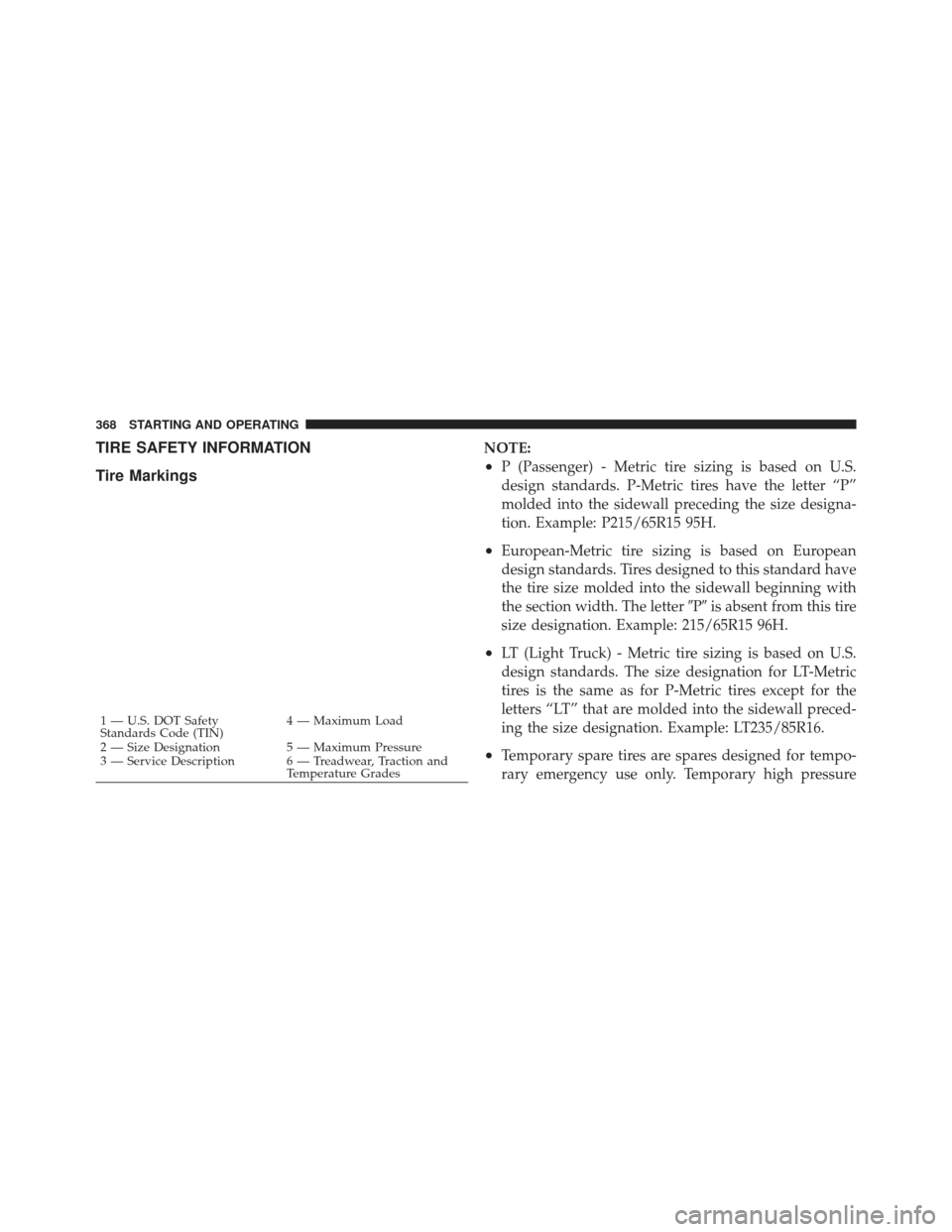
TIRE SAFETY INFORMATION
Tire MarkingsNOTE:
•P (Passenger) - Metric tire sizing is based on U.S.
design standards. P-Metric tires have the letter “P”
molded into the sidewall preceding the size designa-
tion. Example: P215/65R15 95H.
•European-Metric tire sizing is based on European
design standards. Tires designed to this standard have
the tire size molded into the sidewall beginning with
the section width. The letter�P�is absent from this tire
size designation. Example: 215/65R15 96H.
•LT (Light Truck) - Metric tire sizing is based on U.S.
design standards. The size designation for LT-Metric
tires is the same as for P-Metric tires except for the
letters “LT” that are molded into the sidewall preced-
ing the size designation. Example: LT235/85R16.
•Temporary spare tires are spares designed for tempo-
rary emergency use only. Temporary high pressure
1 — U.S. DOT Safety
Standards Code (TIN) 4 — Maximum Load
2 — Size Designation 5 — Maximum Pressure
3 — Service Description 6 — Treadwear, Traction and Temperature Grades
368 STARTING AND OPERATING
Page 372 of 558
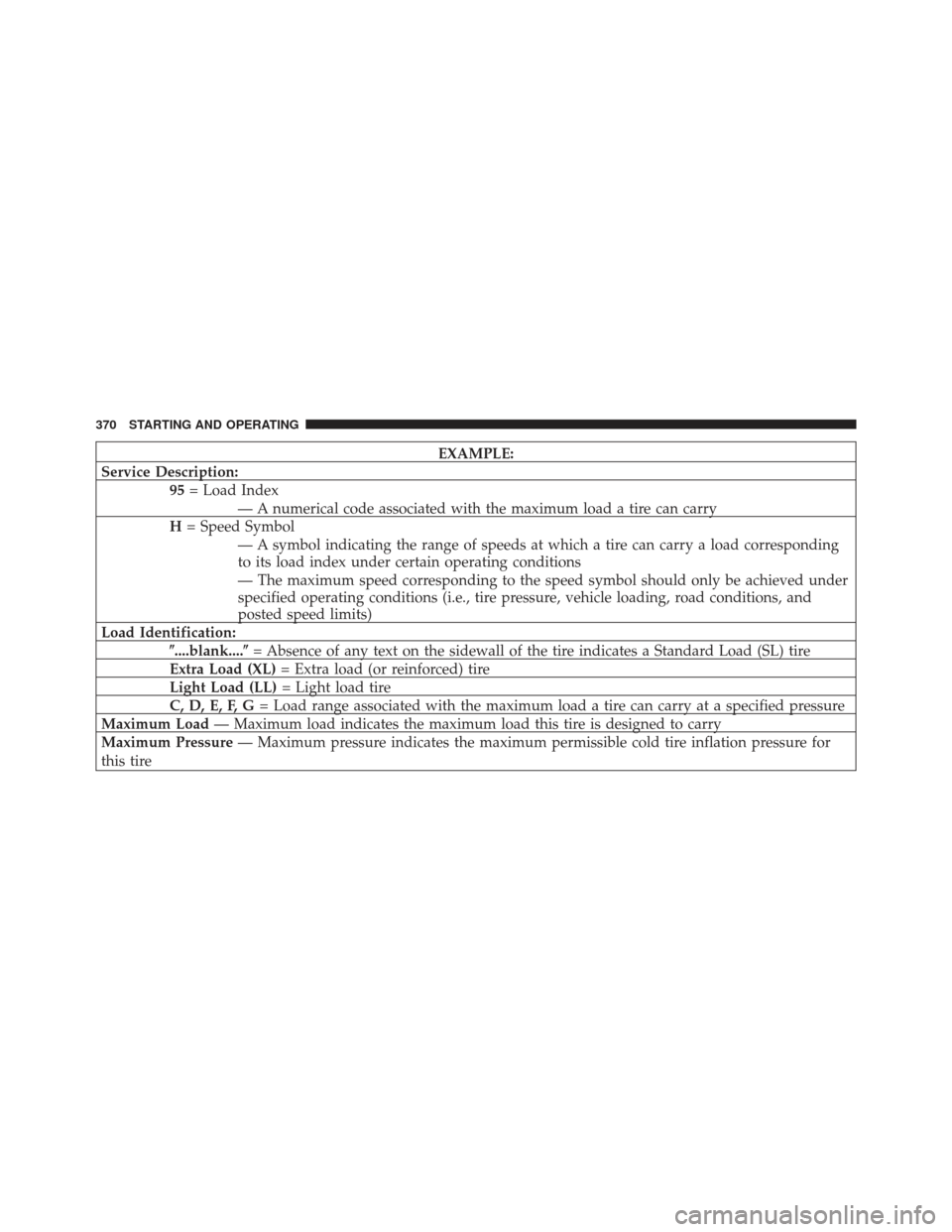
EXAMPLE:
Service Description: 95= Load Index
— A numerical code associated with the maximum load a tire can carry
H = Speed Symbol
— A symbol indicating the range of speeds at which a tire can carry a load corresponding
to its load index under certain operating conditions
— The maximum speed corresponding to the speed symbol should only be achieved under
specified operating conditions (i.e., tire pressure, vehicle loading, road conditions, and
posted speed limits)
Load Identification: �....blank....� = Absence of any text on the sidewall of the tire indicates a Standard Load (SL) tire
Extra Load (XL) = Extra load (or reinforced) tire
Light Load (LL) = Light load tire
C, D, E, F, G = Load range associated with the maximum load a tire can carry at a specified pressure
Maximum Load — Maximum load indicates the maximum load this tire is designed to carry
Maximum Pressure — Maximum pressure indicates the maximum permissible cold tire inflation pressure for
this tire
370 STARTING AND OPERATING
Page 386 of 558
Tread Wear Indicators
Tread wear indicators are in the original equipment tires
to help you in determining when your tires should be
replaced.These indicators are molded into the bottom of the tread
grooves. They will appear as bands when the tread depth
becomes 1/16 in (2 mm). When the tread is worn to the
tread wear indicators, the tire should be replaced.
CAUTION!
Proper operation of four-wheel drive vehicles de-
pends on tires of equal size, type and circumference
on each wheel. Any difference in tire size can cause
damage to the transfer case. Tire rotation schedule
should be followed to balance tire wear.
Life Of Tire
The service life of a tire is dependent upon various
factors including but not limited to:
•Driving style
•Tire pressure
1—WornTire
2—NewTire
384 STARTING AND OPERATING