Page 251 of 558
Elapsed Time
Shows the total elapsed time of travel since the last reset.
Elapsed time will increment when the ignition switch is
in the RUN or START position.
Elapsed time is displayed as follows:
hours:minutes:seconds
Elapsed time can be reset by pressing and holding the
SELECT button (as prompted in the EVIC display). Upon
reset all digits will change to zeros and time will start
incrementing again if the ignition switch is in RUN or
START.
EVIC Units Selection (UNITS IN Display)
Displays the units used for the Outside Temperature,
Average Fuel Economy, Distance to Empty and Tire
Pressure features. Press and release the SELECT button to
toggle units between�U.S.�and�METRIC�.
System Status
Displays SYSTEM OK if there are no active Warning
Messages stored. Pressing and releasing the DOWN
button when SYSTEM OK is displayed will do nothing.
Displays SYSTEM WARNINGS PRESENT if there are
active Warning Messages stored. Pressing and releasing
the DOWN button when SYSTEM WARNINGS PRES-
ENT is displayed will display each stored warning for
each button press. Press and Release the MENU button to
return to the Main Menu.
Personal Settings
(Customer-Programmable Features)
Personal Settings allows the driver to set and recall
features when the vehicle speed is at 0 mph (0 km/h)
(manual transmission) or when the shift lever is in PARK
(auto transmission).
Press and release the MENU button until Personal Set-
tings displays in the EVIC then press the SELECT button.
4
UNDERSTANDING YOUR INSTRUMENT PANEL 249
Page 255 of 558
make your selection, press and release the SELECT
button. Refer to “Rear Park Assist System” in “Under-
standing The Features Of Your Vehicle” for system func-
tion and operating information.
Hill Start Assist (HSA) — If Equipped
When on is selected, the HSA system is active. Refer to
“Electronic Brake Control System” in “Starting And
Operating” for system function and operating informa-
tion. To make your selection, press and release the
SELECT button until “ON” or “OFF” appears.
Rain Sensing Intermittent Wipers — If Equipped
When ON is selected, the system will automatically
activate the windshield wipers if it senses moisture on
the windshield. To make your selection, press and release
the SELECT button until “ON” or “OFF” appears. When
OFF is selected, the system reverts to the standard
intermittent wiper operation.
Display Units In
The EVIC can be changed between English and Metric
units of measure. The units apply to the Outside Tem-
perature, Average Fuel Economy, Distance to Empty, and
Tire Pressure displays. To make your selection, press and
release the SELECT button until “U.S.” or�METRIC�
appears.
Display Fuel Saver — If Equipped
The “ECO” message is located in the Compass/
Temperature display; this message can be turned on or
off. To make your selection, press and release the SELECT
button until “ON” or “OFF” appears.
Compass Variance
Refer to “Compass Display” for more information.
Calibrate Compass
Refer to “Compass Display” for more information.
4
UNDERSTANDING YOUR INSTRUMENT PANEL 253
Page 318 of 558
�Off-Road Driving Tips .................. 345
▫ When To Use 4WD Low Range .......... 345
▫ Driving Through Water ................ 345
▫ Driving In Snow, Mud And Sand ......... 346
▫ Hill Climbing ....................... 347
▫ Traction Downhill .................... 348
▫ After Driving Off-Road ................ 348
� Power Steering ....................... 349
▫ Power Steering Fluid Check ............. 350
� Parking Brake ........................ 351
� Anti-Lock Brake System ................. 353
� Electronic Brake Control System ........... 355
▫ Anti-Lock Brake System (ABS) ........... 356▫
Traction Control System (TCS) ........... 356
▫ Brake Assist System (BAS) .............. 357
▫ Electronic Roll Mitigation (ERM) ......... 358
▫ Hill Start Assist (HSA) ................ 358
▫ Hill Descent Control (HDC) – If Equipped . . 361
▫ Electronic Stability Control (ESC) ......... 363
▫ ESC Activation/Malfunction Indicator Light
And ESC Off Indicator Light ............ 366
� Tire Safety Information ................. 368
▫ Tire Markings ....................... 368
▫ Tire Identification Number (TIN) ......... 371
▫ Tire Terminology And Definitions ......... 372
▫ Tire Loading And Tire Pressure .......... 373
316 STARTING AND OPERATING
Page 319 of 558
�Tires — General Information ............. 377
▫ Tire Pressure ....................... 377
▫ Tire Inflation Pressures ................ 378
▫ Tire Pressures For High Speed Operation . . . 380
▫ Radial-Ply Tires ..................... 380
▫ Spare Tire Matching Original Equipped Tire
And Wheel – If Equipped .............. 380
▫ Compact Spare Tire – If Equipped ........ 381
▫ Full Size Spare – If Equipped ............ 382
▫ Limited-Use Spare – If Equipped ......... 382
▫ Tire Spinning ....................... 383
▫ Tread Wear Indicators ................. 384
▫ Life Of Tire ........................ 384 ▫
Replacement Tires .................... 385
� Tire Chains .......................... 386
� Tire Rotation Recommendations ........... 388
� Tire Pressure Monitor System (TPMS) ....... 389
▫ Base System ........................ 391
▫ Premium System – If Equipped .......... 394
▫ General Information .................. 399
� Fuel Requirements ..................... 399
▫ Reformulated Gasoline ................ 400
▫ Gasoline/Oxygenate Blends ............. 400
▫ E-85 Usage In Non-Flex Fuel Vehicles ...... 401
▫ MMT In Gasoline .................... 401
▫ Materials Added To Fuel ............... 402
5
STARTING AND OPERATING 317
Page 339 of 558
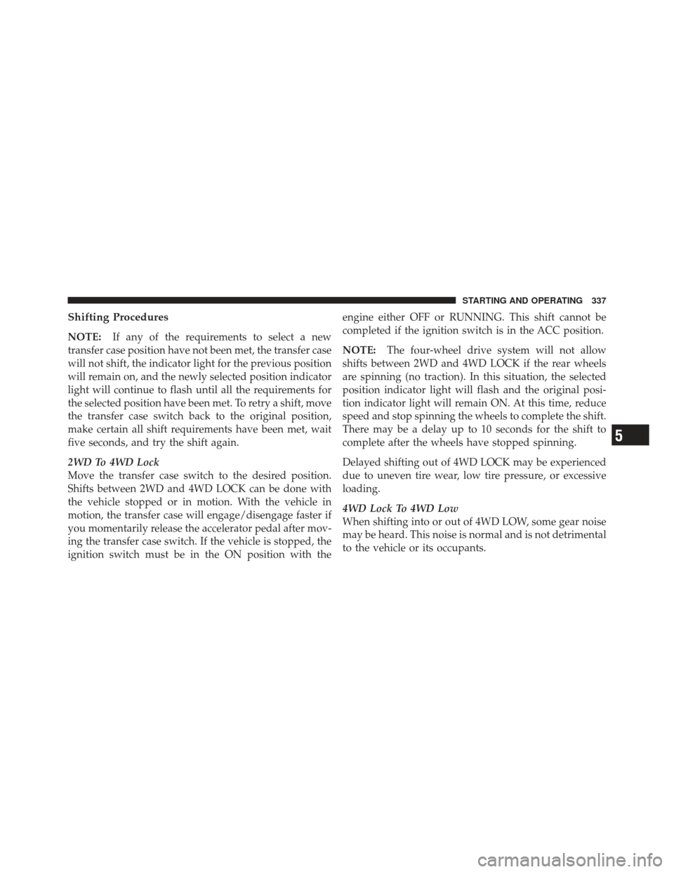
Shifting Procedures
NOTE:If any of the requirements to select a new
transfer case position have not been met, the transfer case
will not shift, the indicator light for the previous position
will remain on, and the newly selected position indicator
light will continue to flash until all the requirements for
the selected position have been met. To retry a shift, move
the transfer case switch back to the original position,
make certain all shift requirements have been met, wait
five seconds, and try the shift again.
2WD To 4WD Lock
Move the transfer case switch to the desired position.
Shifts between 2WD and 4WD LOCK can be done with
the vehicle stopped or in motion. With the vehicle in
motion, the transfer case will engage/disengage faster if
you momentarily release the accelerator pedal after mov-
ing the transfer case switch. If the vehicle is stopped, the
ignition switch must be in the ON position with the engine either OFF or RUNNING. This shift cannot be
completed if the ignition switch is in the ACC position.
NOTE:
The four-wheel drive system will not allow
shifts between 2WD and 4WD LOCK if the rear wheels
are spinning (no traction). In this situation, the selected
position indicator light will flash and the original posi-
tion indicator light will remain ON. At this time, reduce
speed and stop spinning the wheels to complete the shift.
There may be a delay up to 10 seconds for the shift to
complete after the wheels have stopped spinning.
Delayed shifting out of 4WD LOCK may be experienced
due to uneven tire wear, low tire pressure, or excessive
loading.
4WD Lock To 4WD Low
When shifting into or out of 4WD LOW, some gear noise
may be heard. This noise is normal and is not detrimental
to the vehicle or its occupants.
5
STARTING AND OPERATING 337
Page 355 of 558
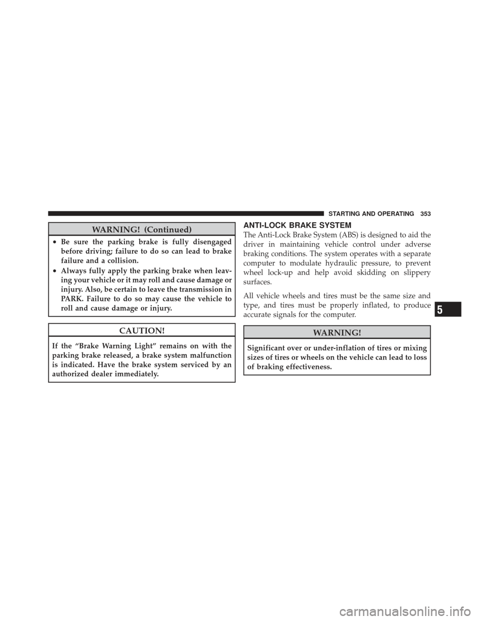
WARNING! (Continued)
•Be sure the parking brake is fully disengaged
before driving; failure to do so can lead to brake
failure and a collision.
•Always fully apply the parking brake when leav-
ing your vehicle or it may roll and cause damage or
injury. Also, be certain to leave the transmission in
PARK. Failure to do so may cause the vehicle to
roll and cause damage or injury.
CAUTION!
If the “Brake Warning Light” remains on with the
parking brake released, a brake system malfunction
is indicated. Have the brake system serviced by an
authorized dealer immediately.
ANTI-LOCK BRAKE SYSTEM
The Anti-Lock Brake System (ABS) is designed to aid the
driver in maintaining vehicle control under adverse
braking conditions. The system operates with a separate
computer to modulate hydraulic pressure, to prevent
wheel lock-up and help avoid skidding on slippery
surfaces.
All vehicle wheels and tires must be the same size and
type, and tires must be properly inflated, to produce
accurate signals for the computer.
WARNING!
Significant over or under-inflation of tires or mixing
sizes of tires or wheels on the vehicle can lead to loss
of braking effectiveness.
5
STARTING AND OPERATING 353
Page 370 of 558
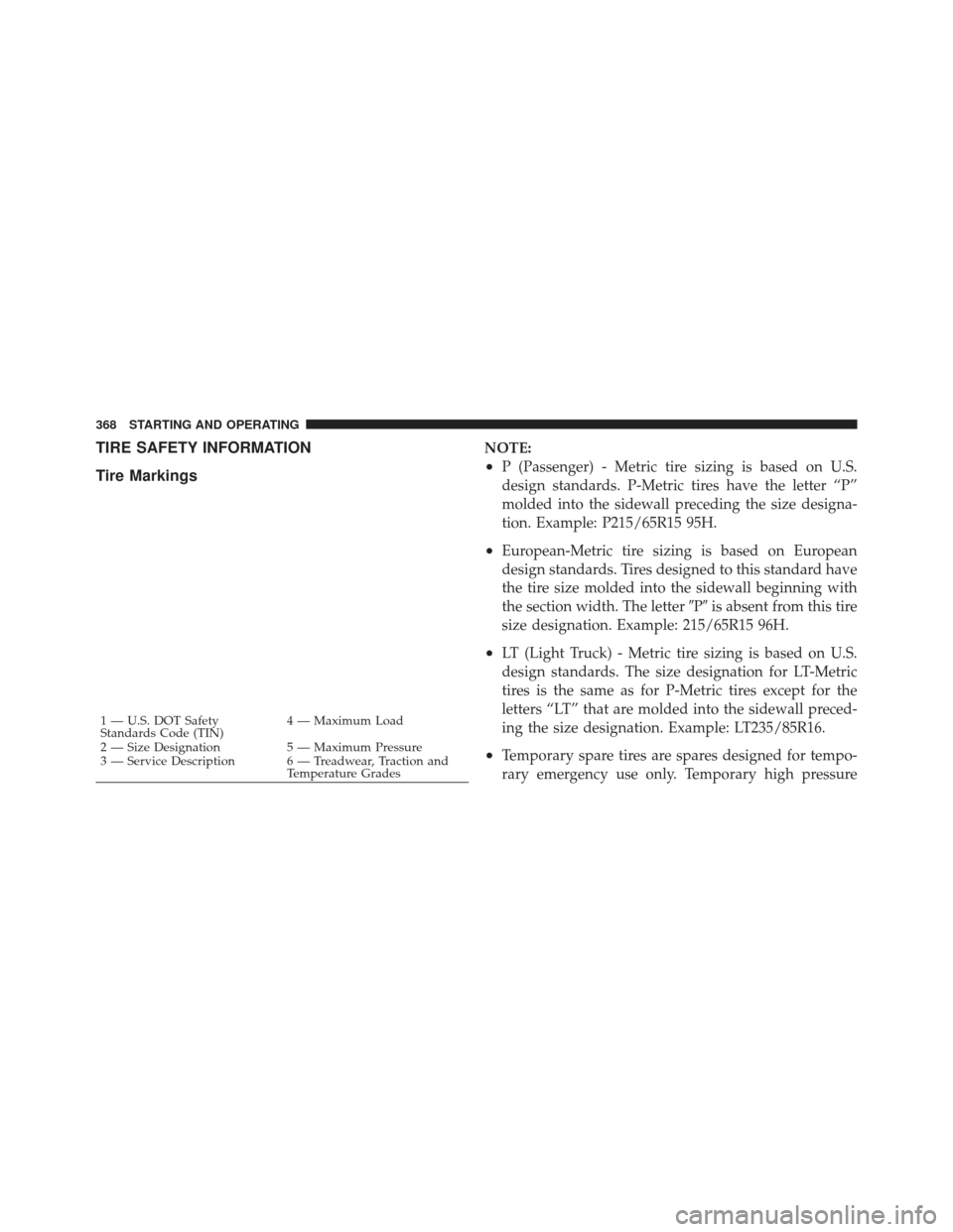
TIRE SAFETY INFORMATION
Tire MarkingsNOTE:
•P (Passenger) - Metric tire sizing is based on U.S.
design standards. P-Metric tires have the letter “P”
molded into the sidewall preceding the size designa-
tion. Example: P215/65R15 95H.
•European-Metric tire sizing is based on European
design standards. Tires designed to this standard have
the tire size molded into the sidewall beginning with
the section width. The letter�P�is absent from this tire
size designation. Example: 215/65R15 96H.
•LT (Light Truck) - Metric tire sizing is based on U.S.
design standards. The size designation for LT-Metric
tires is the same as for P-Metric tires except for the
letters “LT” that are molded into the sidewall preced-
ing the size designation. Example: LT235/85R16.
•Temporary spare tires are spares designed for tempo-
rary emergency use only. Temporary high pressure
1 — U.S. DOT Safety
Standards Code (TIN) 4 — Maximum Load
2 — Size Designation 5 — Maximum Pressure
3 — Service Description 6 — Treadwear, Traction and Temperature Grades
368 STARTING AND OPERATING
Page 372 of 558
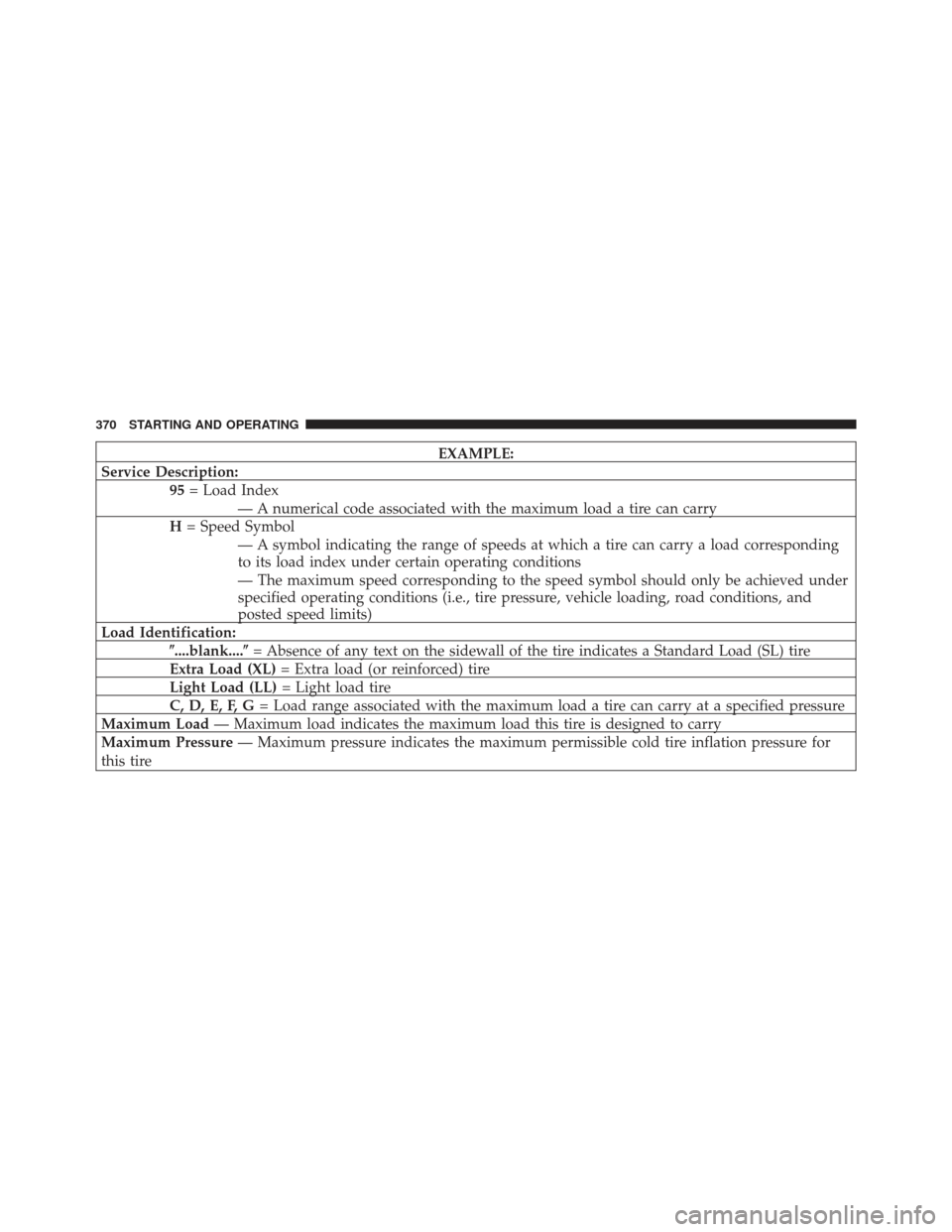
EXAMPLE:
Service Description: 95= Load Index
— A numerical code associated with the maximum load a tire can carry
H = Speed Symbol
— A symbol indicating the range of speeds at which a tire can carry a load corresponding
to its load index under certain operating conditions
— The maximum speed corresponding to the speed symbol should only be achieved under
specified operating conditions (i.e., tire pressure, vehicle loading, road conditions, and
posted speed limits)
Load Identification: �....blank....� = Absence of any text on the sidewall of the tire indicates a Standard Load (SL) tire
Extra Load (XL) = Extra load (or reinforced) tire
Light Load (LL) = Light load tire
C, D, E, F, G = Load range associated with the maximum load a tire can carry at a specified pressure
Maximum Load — Maximum load indicates the maximum load this tire is designed to carry
Maximum Pressure — Maximum pressure indicates the maximum permissible cold tire inflation pressure for
this tire
370 STARTING AND OPERATING