Page 226 of 558
INSTRUMENT CLUSTER DESCRIPTIONS
1. Fuel Gauge
The fuel gauge shows level of fuel in tank when ignition
switch is in the ON/RUN position.
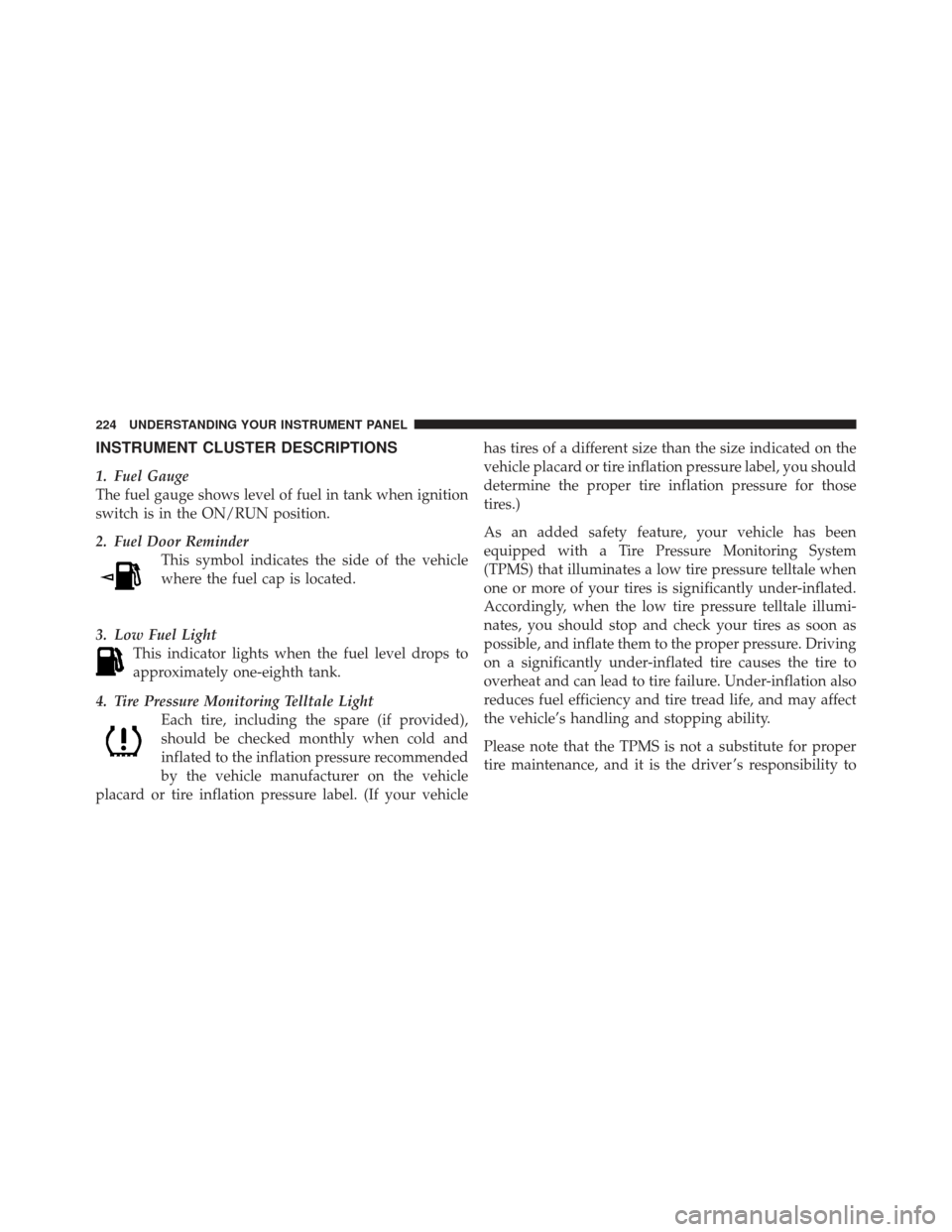
2. Fuel Door ReminderThis symbol indicates the side of the vehicle
where the fuel cap is located.
3. Low Fuel Light This indicator lights when the fuel level drops to
approximately one-eighth tank.
4. Tire Pressure Monitoring Telltale Light Each tire, including the spare (if provided),
should be checked monthly when cold and
inflated to the inflation pressure recommended
by the vehicle manufacturer on the vehicle
placard or tire inflation pressure label. (If your vehicle has tires of a different size than the size indicated on the
vehicle placard or tire inflation pressure label, you should
determine the proper tire inflation pressure for those
tires.)
As an added safety feature, your vehicle has been
equipped with a Tire Pressure Monitoring System
(TPMS) that illuminates a low tire pressure telltale when
one or more of your tires is significantly under-inflated.
Accordingly, when the low tire pressure telltale illumi-
nates, you should stop and check your tires as soon as
possible, and inflate them to the proper pressure. Driving
on a significantly under-inflated tire causes the tire to
overheat and can lead to tire failure. Under-inflation also
reduces fuel efficiency and tire tread life, and may affect
the vehicle’s handling and stopping ability.
Please note that the TPMS is not a substitute for proper
tire maintenance, and it is the driver ’s responsibility to
224 UNDERSTANDING YOUR INSTRUMENT PANEL
Page 227 of 558
maintain correct tire pressure, even if under-inflation has
not reached the level to trigger illumination of the TPMS
low tire pressure telltale.
Your vehicle has also been equipped with a TPMS
malfunction indicator to indicate when the system is not
operating properly. The TPMS malfunction indicator is
combined with the low tire pressure telltale. When the
system detects a malfunction, the telltale will flash for
approximately one minute and then remain continuously
illuminated. This sequence will continue upon subse-
quent vehicle start-ups as long as the malfunction exists.
When the malfunction indicator is illuminated, the sys-
tem may not be able to detect or signal low tire pressure
as intended. TPMS malfunctions may occur for a variety
of reasons, including the installation of replacement or
alternate tires or wheels on the vehicle that prevent the
TPMS from functioning properly. Always check the
TPMS malfunction telltale after replacing one or moretires or wheels on your vehicle, to ensure that the
replacement or alternate tires and wheels allow the TPMS
to continue to function properly.
CAUTION!
The TPMS has been optimized for the original
equipment tires and wheels. TPMS pressures and
warning have been established for the tire size
equipped on your vehicle. Undesirable system opera-
tion or sensor damage may result when using re-
placement equipment that is not of the same size,
type, and/or style. Aftermarket wheels can cause
sensor damage. Do not use tire sealant from a can or
balance beads if your vehicle is equipped with a
TPMS, as damage to the sensors may result.
4
UNDERSTANDING YOUR INSTRUMENT PANEL 225
Page 319 of 558
�Tires — General Information ............. 377
▫ Tire Pressure ....................... 377
▫ Tire Inflation Pressures ................ 378
▫ Tire Pressures For High Speed Operation . . . 380
▫ Radial-Ply Tires ..................... 380
▫ Spare Tire Matching Original Equipped Tire
And Wheel – If Equipped .............. 380
▫ Compact Spare Tire – If Equipped ........ 381
▫ Full Size Spare – If Equipped ............ 382
▫ Limited-Use Spare – If Equipped ......... 382
▫ Tire Spinning ....................... 383
▫ Tread Wear Indicators ................. 384
▫ Life Of Tire ........................ 384 ▫
Replacement Tires .................... 385
� Tire Chains .......................... 386
� Tire Rotation Recommendations ........... 388
� Tire Pressure Monitor System (TPMS) ....... 389
▫ Base System ........................ 391
▫ Premium System – If Equipped .......... 394
▫ General Information .................. 399
� Fuel Requirements ..................... 399
▫ Reformulated Gasoline ................ 400
▫ Gasoline/Oxygenate Blends ............. 400
▫ E-85 Usage In Non-Flex Fuel Vehicles ...... 401
▫ MMT In Gasoline .................... 401
▫ Materials Added To Fuel ............... 402
5
STARTING AND OPERATING 317
Page 336 of 558
CAUTION! (Continued)
•The 4WD LOCK position and 4WD LOW position
are intended for loose or slippery road surfaces
only. Driving in these positions on dry hard-
surfaced roads may cause increased tire wear and
damage to the driveline components.
•When operating your vehicle in 4WD LOW, the
engine speed is approximately three times that of
the 2WD position or 4WD LOCK position at a
given road speed. Take care not to over-speed the
engine and do not exceed 25 mph (40 km/h).
•Proper operation of four-wheel drive vehicles de-
pends on tires of equal size, type, and circumfer-
ence on each wheel. Any difference in tire size can
cause damage to the transfer case. Tire rotation
schedule should be followed to balance tire wear.
WARNING!
•You or others could be injured if you leave the
vehicle unattended with the transfer case in the
NEUTRAL position without first fully engaging
the parking brake. The transfer case NEUTRAL
position disengages both the front driveshaft and
rear driveshaft from the powertrain and it will
allow the vehicle to move even if the transmission
is in PARK. The parking brake should always be
applied when the driver is not in the vehicle.
•Always engage the parking brake when powering
down the vehicle if the “SERV 4WD Warning
Light” is illuminated. Not engaging the parking
brake may allow the vehicle to roll, which may
cause personal injury.(Continued)
334 STARTING AND OPERATING
Page 342 of 558
CAUTION! (Continued)
•When operating your vehicle in 4WD LOW, the
engine speed is approximately three times that of
the 2WD position or 4WD AUTO position at a
given road speed. Take care not to over-speed the
engine and do not exceed 25 mph (40 km/h).
•Proper operation of four-wheel drive vehicles de-
pends on tires of equal size, type, and circumfer-
ence on each wheel. Any difference in tire size can
cause damage to the transfer case. Tire rotation
schedule should be followed to balance tire wear.
WARNING!
•You or others could be injured if you leave the
vehicle unattended with the transfer case in the
NEUTRAL position without first fully engaging
the parking brake. The transfer case NEUTRAL
position disengages both the front driveshaft and
rear driveshaft from the powertrain and it will
allow the vehicle to move despite the transmission
position. The parking brake should always be
applied when the driver is not in the vehicle.
•Always engage the parking brake when powering
down the vehicle if the “SERV 4WD Warning
Light” is illuminated. Not engaging the parking
brake may allow the vehicle to roll, which may
cause personal injury.(Continued)
340 STARTING AND OPERATING
Page 355 of 558
WARNING! (Continued)
•Be sure the parking brake is fully disengaged
before driving; failure to do so can lead to brake
failure and a collision.
•Always fully apply the parking brake when leav-
ing your vehicle or it may roll and cause damage or
injury. Also, be certain to leave the transmission in
PARK. Failure to do so may cause the vehicle to
roll and cause damage or injury.
CAUTION!
If the “Brake Warning Light” remains on with the
parking brake released, a brake system malfunction
is indicated. Have the brake system serviced by an
authorized dealer immediately.
ANTI-LOCK BRAKE SYSTEM
The Anti-Lock Brake System (ABS) is designed to aid the
driver in maintaining vehicle control under adverse
braking conditions. The system operates with a separate
computer to modulate hydraulic pressure, to prevent
wheel lock-up and help avoid skidding on slippery
surfaces.
All vehicle wheels and tires must be the same size and
type, and tires must be properly inflated, to produce
accurate signals for the computer.
WARNING!
Significant over or under-inflation of tires or mixing
sizes of tires or wheels on the vehicle can lead to loss
of braking effectiveness.
5
STARTING AND OPERATING 353
Page 370 of 558
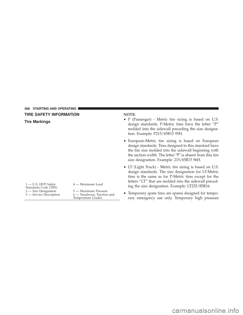
TIRE SAFETY INFORMATION
Tire MarkingsNOTE:
•P (Passenger) - Metric tire sizing is based on U.S.
design standards. P-Metric tires have the letter “P”
molded into the sidewall preceding the size designa-
tion. Example: P215/65R15 95H.
•European-Metric tire sizing is based on European
design standards. Tires designed to this standard have
the tire size molded into the sidewall beginning with
the section width. The letter�P�is absent from this tire
size designation. Example: 215/65R15 96H.
•LT (Light Truck) - Metric tire sizing is based on U.S.
design standards. The size designation for LT-Metric
tires is the same as for P-Metric tires except for the
letters “LT” that are molded into the sidewall preced-
ing the size designation. Example: LT235/85R16.
•Temporary spare tires are spares designed for tempo-
rary emergency use only. Temporary high pressure
1 — U.S. DOT Safety
Standards Code (TIN) 4 — Maximum Load
2 — Size Designation 5 — Maximum Pressure
3 — Service Description 6 — Treadwear, Traction and Temperature Grades
368 STARTING AND OPERATING
Page 371 of 558
compact spare tires have the letter “T” or “S” molded
into the sidewall preceding the size designation. Ex-
ample: T145/80D18 103M.•High flotation tire sizing is based on U.S. design
standards and it begins with the tire diameter molded
into the sidewall. Example: 31x10.5 R15 LT.
Tire Sizing Chart
EXAMPLE:
Size Designation:
P= Passenger car tire size based on U.S. design standards
�....blank....� = Passenger car tire based on European design standards
LT = Light truck tire based on U.S. design standards
TorS= Temporary spare tire
31 = Overall diameter in inches (in)
215 = Section width in millimeters (mm)
65 = Aspect ratio in percent (%)
— Ratio of section height to section width of tire
10.5 = Section width in inches (in)
R = Construction code
—�R� means radial construction
— �D� means diagonal or bias construction
15 = Rim diameter in inches (in)
5
STARTING AND OPERATING 369