Page 160 of 411

Features of your vehicle78
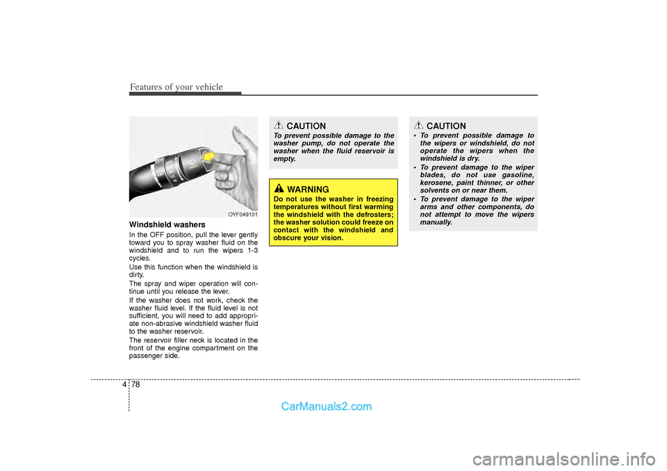
4Windshield washers In the OFF position, pull the lever gently
toward you to spray washer fluid on the
windshield and to run the wipers 1-3
cycles.
Use this function when the windshield is
dirty.
The spray and wiper operation will con-
tinue until you release the lever.
If the washer does not work, check the
washer fluid level. If the fluid level is not
sufficient, you will need to add appropri-
ate non-abrasive windshield washer fluid
to the washer reservoir.
The reservoir filler neck is located in the
front of the engine compartment on the
passenger side.
CAUTION
To prevent possible damage to the
washer pump, do not operate thewasher when the fluid reservoir isempty.
WARNING
Do not use the washer in freezing
temperatures without first warming
the windshield with the defrosters;
the washer solution could freeze on
contact with the windshield and
obscure your vision.
CAUTION
To prevent possible damage to the wipers or windshield, do notoperate the wipers when thewindshield is dry.
To prevent damage to the wiper blades, do not use gasoline,kerosene, paint thinner, or othersolvents on or near them.
To prevent damage to the wiper arms and other components, donot attempt to move the wipersmanually.
OYF049101
Page 167 of 411
485
Features of your vehicle
Mode selectionType A
The mode selection button controls the
direction of the air flow through the venti-
lation system.
The air flow outlet port is converted as
follows:
Face-Level (B, D, E C, F)
Air flow is directed toward the upper body
and face. Additionally, each outlet can be
controlled to direct the air discharged
from the outlet.
Bi-Level (B, D, E, C, F)
Air flow is directed towards the face and
the floor.
Floor-Level (C, A, D, E)
Most of the air flow is directed to the
floor, with a small amount of the air being
directed to the windshield and side win-
dow defrosters.
Floor/Defrost-Level (A, C, D, E)
Most of the air flow is directed to the floor
and the windshield with a small amount
directed to the side window defrosters.
Defrost-Level (A, D)
Most of the air flow is directed to the
windshield with a small amount of air
directed to the side window defrosters.
OYF049112
■Type A
Page 168 of 411
Features of your vehicle86
4Type B
If you push the button once, the corre-
sponding switch will turn on, and if you
push the button again, the switch will turn
off. Defrost-Level (A, D)
(Button 1)
Most of the air flow is directed to the
windshield.
Face-Level (B, C, D, E, F)
(Button 2)
Air flow is directed toward the upper body
and face.
Additionally, each outlet can be con-
trolled to direct the air discharged from
the outlet.
Floor-Level (A, C, D, E)
(Button 3)
Most of the air flow is directed to the
floor. Also you may select 2~3 modes at the
same time for desired air flow.
Defrost & Face Level
(Button 1 and 2)
Defrost & Floor Level
(Button 1 and 3)
Face & Floor Level
(Button 2 and 3)
All mode (Button 1, 2 and 3)
OYF042112N
■Type B
Page 169 of 411
487
Features of your vehicle
MAX A/C-Level (B, D)To operate the MAX A/C, turn the tem-
perature knob to extreme left. Air flow is
directed toward the upper body and face.
In this mode, the air conditioning and the
recirculated air position will be selected
automatically.Instrument panel vents
The outlet vents can be opened or closed
separately using the thumbwheel.
Also, you can adjust the direction of air
delivered from these vents using the vent
control lever as shown.
Temperature controlThe temperature control knob allows you
to control the temperature of the air flow-
ing from the ventilation system. To
change the air temperature in the pas-
senger compartment, turn the knob to
the right for warm air or left for cooler air.
OYF049113
OYF049115
OYF049116
Page 177 of 411

495
Features of your vehicle
Manual heating and air condition-
ingThe heating and cooling system can be
controlled manually by pressing buttons
or turning knob(s) other than the AUTO
button. In this case, the system works
sequentially according to the order of
buttons or knob(s) selected.
1. Start the engine.
2. Set the mode to the desired position.For improving the effectiveness of
heating and cooling;
- Heating:
- Cooling:
3. Set the temperature control to the desired position.
4. Set the air intake control to the outside (fresh) air position.
5. Set the fan speed control to the desired speed.
6. If air conditioning is desired, turn the air conditioning system on.
Press the AUTO button in order to con-
vert to full automatic control of the sys-
tem.
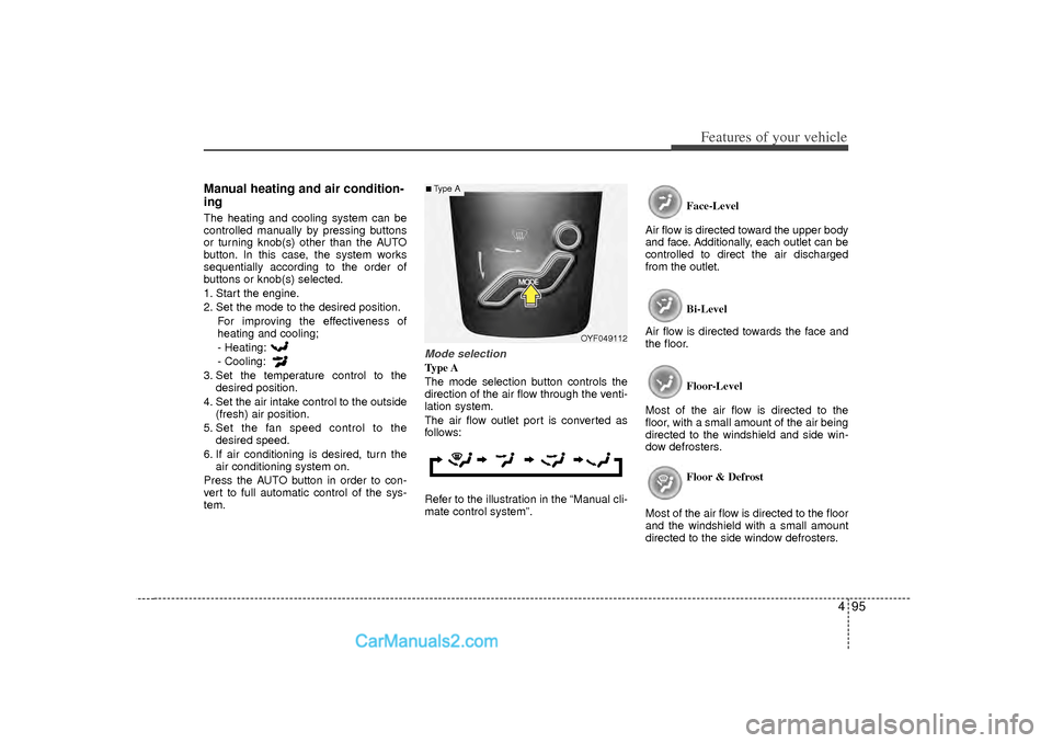
Mode selectionType A
The mode selection button controls the
direction of the air flow through the venti-
lation system.
The air flow outlet port is converted as
follows:
Refer to the illustration in the “Manual cli-
mate control system”. Face-Level
Air flow is directed toward the upper body
and face. Additionally, each outlet can be
controlled to direct the air discharged
from the outlet.
Bi-Level
Air flow is directed towards the face and
the floor.
Floor-Level
Most of the air flow is directed to the
floor, with a small amount of the air being
directed to the windshield and side win-
dow defrosters.
Floor & Defrost
Most of the air flow is directed to the floor
and the windshield with a small amount
directed to the side window defrosters.
OYF049112
■Type A
Page 178 of 411
Features of your vehicle96
4Type B
If you push the button once, the corre-
sponding switch will turn on, and if you
push the button again, the switch will turn
off.
Refer to the illustration in the “Manual cli-
mate control system”. Defrost-Level (Button 1)
Most of the air flow is directed to the
windshield.
Face-Level (Button 2)
Air flow is directed toward the upper body
and face.
Additionally, each outlet can be con-
trolled to direct the air discharged from
the outlet.
Floor-Level (Button 3)
Most of the air flow is directed to the
floor. Also you may select 2~3 modes at the
same time for desired air flow.
Defrost & Face Level
(Button 1 and 2)
Defrost & Floor Level
(Button 1 and 3)
Face & Floor Level
(Button 2 and 3)
All mode (Button 1, 2 and 3)
OYFH041112N
■Type B
Page 205 of 411

4 123
Features of your vehicle
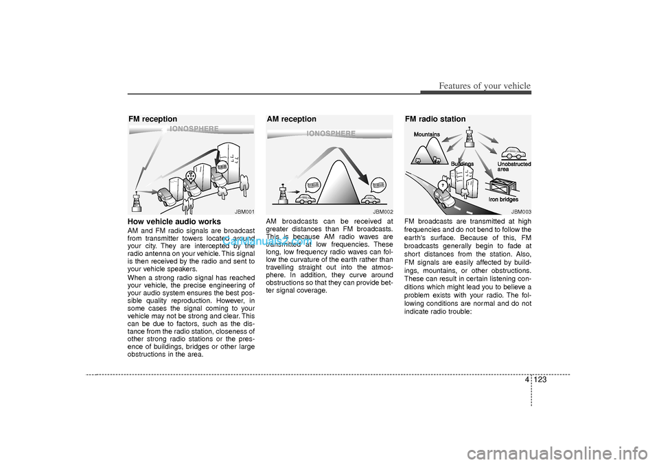
How vehicle audio worksAM and FM radio signals are broadcast
from transmitter towers located around
your city. They are intercepted by the
radio antenna on your vehicle. This signal
is then received by the radio and sent to
your vehicle speakers.
When a strong radio signal has reached
your vehicle, the precise engineering of
your audio system ensures the best pos-
sible quality reproduction. However, in
some cases the signal coming to your
vehicle may not be strong and clear. This
can be due to factors, such as the dis-
tance from the radio station, closeness of
other strong radio stations or the pres-
ence of buildings, bridges or other large
obstructions in the area.AM broadcasts can be received at
greater distances than FM broadcasts.
This is because AM radio waves are
transmitted at low frequencies. These
long, low frequency radio waves can fol-
low the curvature of the earth rather than
travelling straight out into the atmos-
phere. In addition, they curve around
obstructions so that they can provide bet-
ter signal coverage.
FM broadcasts are transmitted at high
frequencies and do not bend to follow the
earth's surface. Because of this, FM
broadcasts generally begin to fade at
short distances from the station. Also,
FM signals are easily affected by build-
ings, mountains, or other obstructions.
These can result in certain listening con-
ditions which might lead you to believe a
problem exists with your radio. The fol-
lowing conditions are normal and do not
indicate radio trouble:
¢�¢� ¢�
¢�¢� ¢�JBM002
AM reception
JBM001
FM reception
JBM003
FM radio station¢�¢�¢�
Page 244 of 411
5
Before driving / 5-3
Key / 5-4
Engine start/stop button / 5-7
Manual transaxle /5-11
Automatic transaxle / 5-14
Brake system / 5-21
Cruise control system / 5-31
Active ECO system / 5-35
Economical operation / 5-36
Special driving conditions / 5-38
Winter driving / 5-42
Vehicle load limit / 5-46
Vehicle weight / 5-51
Trailer towing / 5-52
Driving your vehicle