Page 18 of 403
Your vehicle at a glance
42
ENGINE COMPARTMENT
OYFH071001
❈ The actual engine room in the vehicle may differ from the illustration. 1. Sub relay box ....................................7-53
2. Engine coolant reservoir ...................7-24
3. Windshield washer fluid reservoir .....7-28
4. Radiator cap .....................................7-26
5. Engine oil dipstick .............................7-22
6. Engine oil filler cap ...........................7-22
7. Brake fluid reservoir ..........................7-27
8. Air cleaner.........................................7-29
9. Fuse box ...........................................7-50
10. Inverter coolant ...............................7-24
* : if equipped
Page 110 of 403

429
Features of your vehicle
Electric power steering (EPS)
The power steering uses a motor to
assist you in steering the vehicle. If the
engine is off or if the power steering sys-
tem becomes inoperative, the vehicle
may still be steered, but it will require
increased steering effort.
The motor driven power steering is con-
trolled by a power steering control unit
which senses the steering wheel torque
and vehicle speed to command the
motor.
The steering becomes heavier as the
vehicle’s speed increases and becomes
lighter as the vehicle’s speed decreases
for optimum steering control.
Should you notice any change in the
effort required to steer during normal
vehicle operation, have the power steer-
ing checked by an authorized HYUNDAI
dealer.
✽ ✽NOTICE
The following symptoms may occur dur-
ing normal vehicle operation:
• The EPS warning light does not illumi-
nate.
• The steering effort is high immediately after turning the engine start/stop but-
ton on. This happens as the system
performs the EPS system diagnostics.
When the diagnostics is completed, the
steering wheel will return to its normal
condition.
• A click noise may be heard from the EPS relay after the engine start/stop
button is turned to the ON or LOCK
position.
• A motor noise may be heard when the vehicle is at a stop or at a low driving
speed.
• If the Electric Power Steering System does not operate normally, the warn-
ing light will illuminate on the instru-
ment cluster. The steering wheel may
become difficult to control or operate
abnormally. Take your vehicle to an
authorized HYUNDAI dealer and
have the vehicle checked as soon as
possible.
• When you operate the steering wheel in low temperature, noise could occur.
If temperature rises, the noise will dis-
appear. This is a normal condition.
STEERING WHEEL
CAUTION
If the Electric Power Steering
System does not operate normal-ly, the warning light will illuminateon the instrument cluster. Thesteering wheel may become diffi- cult to control or operate abnor-mally. Take your vehicle to anauthorized HYUNDAI dealer andhave the vehicle checked as soonas possible.
When you operate the steering wheel in low temperature, abnor-mal noise could occur. If tempera-ture rises, the noise will disap-pear. This is a normal condition.
Page 295 of 403
Maintenance
27
ENGINE COMPARTMENT
OYFH071001
❈The actual engine room in the vehicle may differ from the illustration. 1. Sub relay box
2. Engine coolant reservoir
3. Windshield washer fluid reservoir
4. Radiator cap
5. Engine oil dipstick
6. Engine oil filler cap
7. Brake fluid reservoir
8. Air cleaner
9. Fuse box
10. Inverter coolant
* : if equipped
Page 346 of 403

753
Maintenance
Multi fuse
If the multi fuse is blown, it must be
removed as follows:
1. Turn off the engine.
2. Disconnect the negative battery cable.
3. Remove the fuse panel on the rightside in the engine compartment.
4. Remove the nuts shown in the picture above.
5. Replace the fuse with a new one of the same rating.
6. Reinstall in the reverse order of removal.
✽ ✽NOTICE
If the multi fuse is blown, consult an
authorized HYUNDAI dealer.
Oil pump cooling fuse/
Cooling fan fuse
If the oil pump cooling fuse or cooling fan
fuse is blown, it must be removed as fol-
lows:
1. Turn off the engine.
2. Disconnect the negative battery cable.
3. Remove the fuse panel on the right side in the engine compartment.
4. Replace the fuse with a new one of the same rating.
5. Reinstall in the reverse order of removal.
Sub-relay fuse
If the sub-relay fuse is blown, it must be
removed as follows:
1. Turn off the engine.
2. Disconnect the negative battery cable.
3. Replace the fuse with a new one of thesame rating.
4. Reinstall in the reverse order of removal.
OYFH071088NOYFH071089NOYFH071072N
Page 347 of 403
Maintenance
54
7
Inner fuse panel
Engine compartment fuse panel
Fuse/relay panel description
Inside the fuse/relay panel covers, you can find the fuse/relay label describing fuse/relay name and capacity.
OYF079025/OYF071071N/OYF071026N
Sub-relay box
✽
✽NOTICE
Not all fuse panel descriptions in this
manual may be applicable to your vehi-
cle. It is accurate at the time of printing.
When you inspect the fuse panel in your
vehicle, refer to the fuse panel label.
Page 348 of 403

755
Maintenance
Inner fuse panel (Driver’s side fuse panel)
DescriptionFuse rating Protected component
P/SEAT DRI 30A Driver Manual Switch
AMP 30A JBL AMP, AMP
TRUNK 10A I/P Junction Box (Trunk Lid Relay), Fuel Filler Door & Trunk Lid Switch
SAFETY POWER WINDOW 25A Safety Power Window Module
P/WDW LH 25A Power Window Main Switch, Rear Power Window Switch LH
MODULE HEV 7.5A Low DC Converter, Hybrid Inverter, BMS Control Module
BMS 10A BMS Control Module
START 2 7.5A Fob Holder, Start Stop Button Switch, PDM, Stop Lamp Switch, Smart Key Module
MODULE 3 7.5AE/R Fuse & Relay Box (AUX Water Pump Relay), Sport Mode Switch, Key Solenoid,
Active Air Flap
P/WDW RH 25A Power Window Main Switch, Rear Power Window Switch RH
HTD MIRR 10A Driver Power Outside Mirror, Passenger Power Outside Mirror
P/SEAT ASST 20A Passenger Power Seat
S/HEATER FRT 15A Driver Seat Warmer Module, Passenger Seat Warmer Module
PDM 25A PDM
CLOCK 10ASmart Key Module, PDM, BCM, Front Monitor, Clock, Rear Camera Module,
A/V & Navigation Head Unit, Audio, Overhead Console Lamp, AMP, JBL AMP,
Power Outside Mirror Switch
A/CON 7.5A E/R Fuse & Relay Box (Blower Relay), A/C Control Module
S/HTR RR 20A Rear Seat Warmer Switch LH, Rear Seat Warmer Switch RH
SUN ROOF 20A Panorama Sunroof
POWER OUTLET 1 15A Front Power Outlet RH
MODULE 2 7.5A Rear Camera Module, BCM
Spare 20A -
Page 349 of 403

Maintenance
56
7
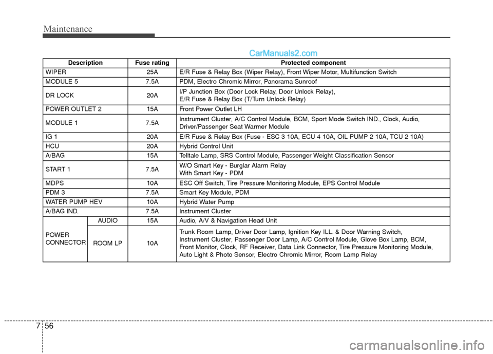
Description Fuse rating Protected component
WIPER 25A E/R Fuse & Relay Box (Wiper Relay), Front Wiper Motor, Multifunction Switch
MODULE 5 7.5A PDM, Electro Chromic Mirror, Panorama Sunroof
DR LOCK 20AI/P Junction Box (Door Lock Relay, Door Unlock Relay),
E/R Fuse & Relay Box (T/Turn Unlock Relay)
POWER OUTLET 2 15A Front Power Outlet LH
MODULE 1 7.5AInstrument Cluster, A/C Control Module, BCM, Sport Mode Switch IND., Clock, Audio,
Driver/Passenger Seat Warmer Module
IG 1 20A E/R Fuse & Relay Box (Fuse - ESC 3 10A, ECU 4 10A, OIL PUMP 2 10A, TCU 2 10A)
HCU 20A Hybrid Control Unit
A/BAG 15A Telltale Lamp, SRS Control Module, Passenger Weight Classification Sensor
START 1 7.5AW/O Smart Key - Burglar Alarm Relay
With Smart Key - PDM
MDPS 10A ESC Off Switch, Tire Pressure Monitoring Module, EPS Control Module
PDM 3 7.5A Smart Key Module, PDM
WATER PUMP HEV 10A Hybrid Water Pump
A/BAG IND. 7.5A Instrument Cluster
POWER
CONNECTOR AUDIO 15A Audio, A/V & Navigation Head Unit
ROOM LP 10A Trunk Room Lamp, Driver Door Lamp, Ignition Key ILL. & Door Warning Switch,
Instrument Cluster, Passenger Door Lamp, A/C Control Module, Glove Box Lamp, BCM,
Front Monitor, Clock, RF Receiver, Data Link Connector, Tire Pressure Monitoring Module,
Auto Light & Photo Sensor, Electro Chromic Mirror, Room Lamp Relay
Page 350 of 403

757
Maintenance
Engine compartment main fuse panel
Description Fuse ratingProtected component
MULTI FUSE B+3
60AI/P Junction Box (Power Window Relay, Fuse - TRUNK 10, S/HEATER FRT 15A,
SAFETY POWER WINDOW 25A, MODULE 3 7.5A, PDM 25A, Power Connector - AUDIO 15A)
IG 1 40A Smart Key - IG 1 Relay, ACC Relay
EMS 40A EMS Box (Fuse - HORN 15A, ECU 3 10A, ECU 1 30A, F/PUMP 20A)
RR HTD 40A RR HTD Relay
BLOWER 40A Blower Relay
B+4 60AI/P Junction Box (Fuse - P/SEAT DRI 30A, AMP 30A, START 2 7.5A, BMS 10A, IPS 2, IPS 3,
IPS 5, IPS 8)
MDPS 80A EPS Control Module
C/FAN LO 40A C/FAN LO Relay
FUSE B+2
50AI/P Junction Box (Fuse - SUNROOF 20A, DR LOCK, IPS 1, IPS 4, IPS 6, IPS 7, IPS 9,
Power Connector - ROOM LP 10A)
WIPER 10A PCM
RR HTD IND 10A A/C Control Module LDC 10A Low DC Converter, Hybrid Inverter
BMS C/FAN 15A BMS Blower Motor Relay TCU 1 20A PCU
STOP LP 15A Stop Lamp Relay, HAC Relay DEICER 20A Deicer Relay ECU 2 20A PCUHCU 20A Hybrid Control
IG 2 30A Smart Key - IG 2 Relay
AHB 1 40A AHB Control Module
OIL PUMP 1 20A Electric Oil Pump Unit