Page 189 of 217
6
DO-IT-YOURSELF MAINTENANCE
37
G270G01HR-GAT Map Light (If installed, With Spectacle Case)
1. Remove the cover with a flat-head
screwdriver.
2. Replace with a new bulb. HHR5039
G270G02HR G270H01HR-GAT Interior Light
(If installed, Without Spectacle Case)
1. Remove the cover with a flat-head
screwdriver. G270H01HR
G270H02HR
2. Replace with a new bulb.
Page 190 of 217
6 DO-IT-YOURSELF MAINTENANCE
38BULB WATTAGES
Interior Light (If installed, Without Spectacle Case) Rear Combination Turn Signal Light
Light Stop/Tail LightBack-up Light
License Plate Light
Part Name
Front Fog Light (If Installed)Front Position Light Headlight (High/Low) Front Turn Signal LightSide Repeater (If Installed) Map Light (If installed, With Spectacle Case) No.
7 8 9
10 11
G280A03HR-GAT
OHR058102
Wattage 27
5
60/55 21
5
10
No. 1
2 3 45 6Wattage
10 21
21/5
165
Part NameSocket Type
PG13
W2.1 x 9.5D P43t-38BA 15s
W2.1 x 9.5D W2.1 x 9.5D Socket Type
S8.5/8.5BA 15s
BAY 15d
W2.1 x 9.5D W2.1 x 9.5D
Page 191 of 217
6
DO-IT-YOURSELF MAINTENANCE
39
BATT
GLOW IGN
ECU
BATT
LAMP
COND ABS2
PTC1 ABS1
PTC2
BLWR PTC3
FFHS
GLOW ALT_SSTOP
HORN
A/CON TCU
ECU1 ECU2
DESCRIPTION
G200C01HR-GAT Engine Compartment
G200C02HR
NOTE:
Not all fuse panel descriptions in this manual may be applicable to your vehicle. It is accurate at the time of printing.
When you inspect the fuse box on your vehicle, refer to the fuse box label. AMPERAGES
100A80A 50A20A50A40A30A 30A40A 30A40A30A 40A 30A10A10A10A10A 10A 10A15A10A CIRCUIT PROTECTED
Generator Glow relay
Start relay, lgnition switchEngine control relay
I/P Fuse box (A/Con, Hazard, DR Lock), Power connector
P/WDW fusible link, Front Fog fuse, Tail lamp relayCondenser fan relayNot usedNot usedNot usedNot usedBlower relayNot usedNot usedECMGeneratorStop lamp switchHorn relayA/Con relayNot usedNot usedNot used
FUSIBLE LINK
FUSE
FUSE PANEL DESCRIPTION
Page 192 of 217
6 DO-IT-YOURSELF MAINTENANCE
40
G200E01HR-GAT Inner Panel
G200E02HR
Page 193 of 217

6
DO-IT-YOURSELF MAINTENANCE
41
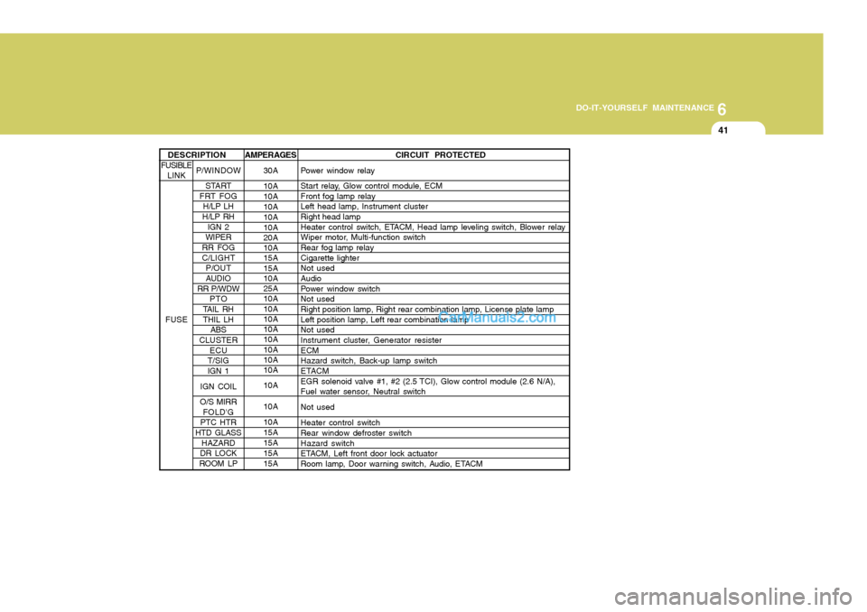
AMPERAGES 30A 10A 10A10A 10A 10A 20A 10A 15A 15A 10A 25A 10A 10A 10A 10A 10A 10A 10A 10A 10A 10A 10A 15A15A15A15A CIRCUIT PROTECTED
Power window relay
Start relay, Glow control module, ECM Front fog lamp relayLeft head lamp, Instrument cluster Right head lamp
Heater control switch, ETACM, Head lamp leveling switch, Blower relay
Wiper motor, Multi-function switch Rear fog lamp relay Cigarette lighterNot used Audio
Power window switchNot used Right position lamp, Right rear combination lamp, License plate lamp Left position lamp, Left rear combination lampNot used
Instrument cluster, Generator resister ECMHazard switch, Back-up lamp switch
ETACM
EGR solenoid valve #1, #2 (2.5 TCI), Glow control module (2.6 N/A),
Fuel water sensor, Neutral switch Not usedHeater control switch Rear window defroster switch Hazard switch
ETACM, Left front door lock actuator
Room lamp, Door warning switch, Audio, ETACM
P/WINDOW START
FRT FOG
H/LP LH
H/LP RH IGN 2
WIPER
RR FOG C/LIGHT P/OUT
AUDIO
RR P/WDW
PTO
TAIL RH THIL LH ABS
CLUSTER ECU
T/SIG IGN 1
IGN COIL
O/S MIRR FOLD'G
PTC HTR
HTD GLASS HAZARD
DR LOCK
ROOM LP
DESCRIPTION
FUSIBLE LINK
FUSE
Page 195 of 217

7EMISSION CONTROL SYSTEMS
2
H020D03HR-GAT
(If Installed)
EMISSION CONTROL SYSTEM
H010A01HR-GAT
(If Installed)
Your Hyundai is equipped with an
emission control system to meet all requirements of the Emission prohibi- tion rules of your province.
In order to assure the proper function
of the emission control systems, it is recommended that you have your car inspected and maintained by an au-thorized Hyundai dealer in accordance with the maintenance schedule in this manual. CATALYTIC CONVERTER
!WARNING:
The exhaust system and catalytic system are very hot while the en-gine is running or immediately after the engine is turned off. Keep away from the exhaust system and cata-lytic, you may get burned.Also, do not remove the heat sinkaround the exhaust system, do notseal the bottom of the vehicle or do not coat the vehicle for corrosion control. It may present a fire riskunder certain conditions.
Exhaust emission control systemThe Exhaust Emission Control Sys-tem is a highly effective system whichcontrols exhaust emissions while main- taining good vehicle performance. Vehicle modifications This vehicle should not be modified.
Modification of your vehicle could af- fect its performance, safety or durabil- ity and may even violate governmentalsafety and emissions regulations.
In addition, damage or performance
problems resulting from any modifica- tion may not be covered under war- ranty.
o If you use unauthorized electronic
devices, it may cause the vehicle tooperate abnormally, wire damage, battery discharge or fire. For your safety, do not use unauthorized elec- tronic devices.
Page 215 of 217

10INDEX
4
G GateRear gate ................................................................. 1-49
Side gate ................................................................. 1-50
General Checks ........................................................... 6-5
Glove Box .................................................................. 1-43
Pen, card and tissue holder ....................................1-43
HHazard Warning Syst em ........................................... 1-38
Headlight Aiming Adjustm ent ...................................... 6-30
Headlight Leveling Device S ystem .............................1-37
Heating and Cooling Control .......................................1-53
Heating and Ventilation ............................................... 1-54
Air flow control ......................................................... 1-54
Air intake control ..................................................... 1-57
Bi-level heating ........................................................ 1-58
Defrost/Defogging .................................................... 1-59
Fan speed control .................................................... 1-56
Temperature control ................................................. 1-56
Higher Speed Motoring ............................................... 2-15
Hood Release ............................................................. 1-47
Horn ............................................................................ 1-52
IIgnition Switch ............................................................. 2-4
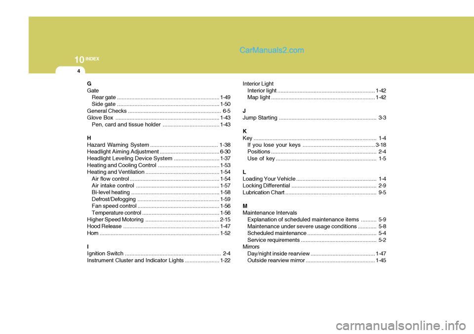
Instrument Cluster and Indicator Lights ...................... 1-22Interior Light
Interior light .............................................................. 1-42
Map light .................................................................. 1-42
JJump Starting .............................................................. 3-3
K
Key .............................................................................. 1-4 If you lose your keys .............................................. 3-18
Positions ................................................................... 2-4
Use of key ................................................................ 1-5
L Loading Your Vehicle ................................................... 1-4
Locking Differential ...................................................... 2-9
Lubrication Chart .......................................................... 9-5
M Maintenance Intervals Explanation of scheduled maintenance items .......... 5-9Maintenance under severe usage conditions ............ 5-8
Scheduled maintenance ............................................ 5-4
Service requirements ................................................ 5-2
Mirrors Day/night inside rearview .................. .......................1-47
Outside rearview mirror............................................ 1-45