2012 FORD F550 warning
[x] Cancel search: warningPage 253 of 448
WARNING: Towing trailers beyond the maximum recommended
gross trailer weight exceeds the limit of the vehicle and could
result in engine damage, transmission damage, structural damage, loss
of vehicle control, vehicle rollover and personal injury.
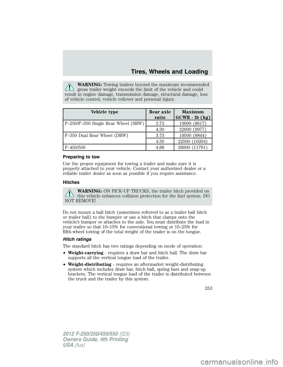
Vehicle type Rear axle
ratio Maximum
GCWR - lb (kg)
F–250/F–350 Single Rear Wheel (SRW) 3.73 19000 (8617)
4.30 22000 (9977)
F–350 Dual Rear Wheel (DRW) 3.73 19500 (8844)
4.30 22500 (10204)
F–450/550 4.88 26000 (11791)
Preparing to tow
Use the proper equipment for towing a trailer and make sure it is
properly attached to your vehicle. Contact your authorized dealer or a
reliable trailer dealer as soon as possible if you require assistance.
Hitches
WARNING: ON PICK-UP TRUCKS, the trailer hitch provided on
this vehicle enhances collision protection for the fuel system. DO
NOT REMOVE!
Do not mount a ball hitch (sometimes referred to as a trailer ball hitch
or trailer ball) to the bumper or use a hitch that clamps onto the
vehicle’s bumper or attaches to the axle. You must distribute the load in
your trailer so that 10–15% for conventional towing or 15–25% for
fifth-wheel towing of the total weight of the trailer is on the tongue.
Hitch ratings
The standard hitch has two ratings depending on mode of operation:
• Weight-carrying - requires a draw bar and hitch ball. The draw bar
supports all the vertical tongue load of the trailer.
• Weight-distributing - requires an aftermarket weight-distributing
system which includes draw bar, hitch ball, spring bars and snap-up
brackets. The vertical tongue load of the trailer is distributed between
the truck and the trailer by this system. Tires, Wheels and Loading
253
2012 F-250/350/450/550 (f23)
Owners Guide, 4th Printing
USA (fus)
Page 254 of 448
To determine which trailer hitch your vehicle is equipped with, refer to
the trailer hitch label located on trailer hitch cross tube. Once you
determine which trailer hitch you have consult your authorized dealer,
the RV and Trailer Towing Guide provided by your dealer or online at
https://www.fleet.ford.com/showroom/rv_trailer_towing/default.asp.
WARNING: The hitch rating listed on the trailer hitch label are
maximum possible trailer ratings for that hitch but may not be
what your vehicle is capable of towing. To find the maximum trailer
weight allowed for your specific vehicle, consult your authorized dealer
(or the RV and Trailer Towing Guide provided by your authorized
dealer).
WARNING: Towing trailers beyond the maximum tongue weight
exceeds the limit of the towing system and could result in
vehicle structural damage, loss of vehicle control and personal injury.
Weight-Distributing Hitches
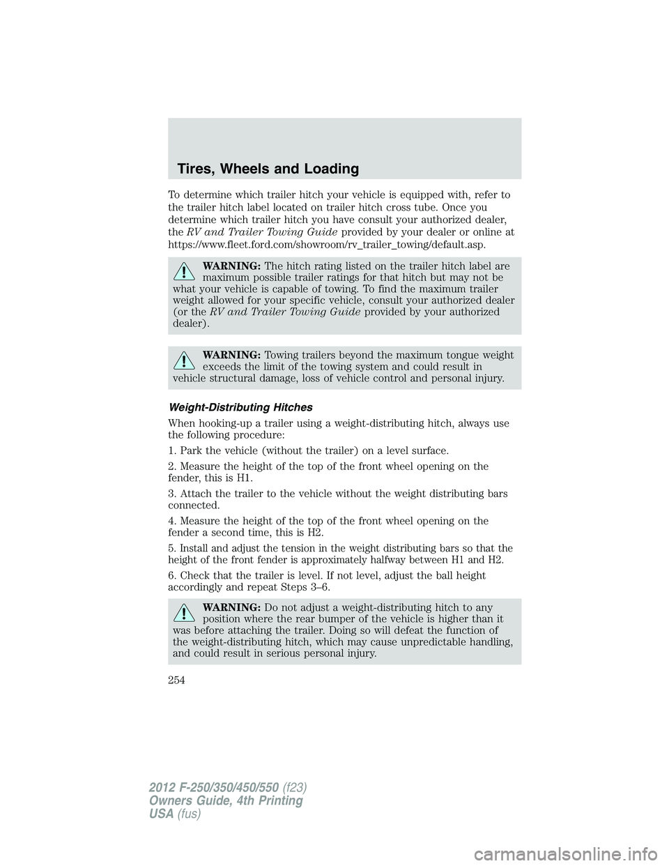
When hooking-up a trailer using a weight-distributing hitch, always use
the following procedure:
1. Park the vehicle (without the trailer) on a level surface.
2. Measure the height of the top of the front wheel opening on the
fender, this is H1.
3. Attach the trailer to the vehicle without the weight distributing bars
connected.
4. Measure the height of the top of the front wheel opening on the
fender a second time, this is H2.
5. Install and adjust the tension in the weight distributing bars so that the
height of the front fender is approximately halfway between H1 and H2.
6. Check that the trailer is level. If not level, adjust the ball height
accordingly and repeat Steps 3–6.
WARNING: Do not adjust a weight-distributing hitch to any
position where the rear bumper of the vehicle is higher than it
was before attaching the trailer. Doing so will defeat the function of
the weight-distributing hitch, which may cause unpredictable handling,
and could result in serious personal injury.Tires, Wheels and Loading
254
2012 F-250/350/450/550 (f23)
Owners Guide, 4th Printing
USA (fus)
Page 255 of 448
Fifth-wheel trailer hitch (if equipped)
To find the maximum trailer weight allowed for your vehicle, consult
your authorized dealer (or the RV and Trailer Towing Guide provided
by your authorized dealer).
Fifth-wheel and gooseneck towing
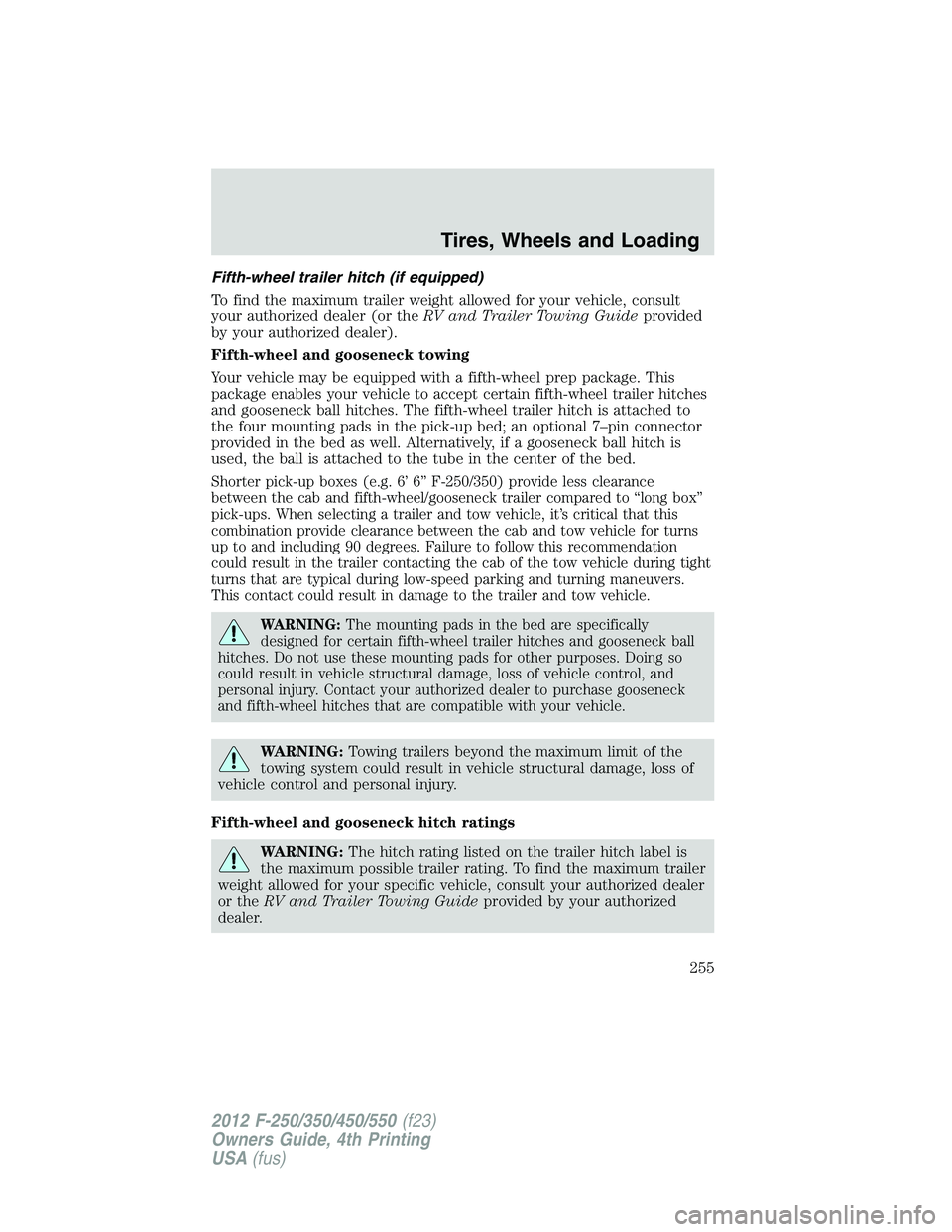
Your vehicle may be equipped with a fifth-wheel prep package. This
package enables your vehicle to accept certain fifth-wheel trailer hitches
and gooseneck ball hitches. The fifth-wheel trailer hitch is attached to
the four mounting pads in the pick-up bed; an optional 7–pin connector
provided in the bed as well. Alternatively, if a gooseneck ball hitch is
used, the ball is attached to the tube in the center of the bed.
Shorter pick-up boxes (e.g. 6’ 6” F-250/350) provide less clearance
between the cab and fifth-wheel/gooseneck trailer compared to “long box”
pick-ups. When selecting a trailer and tow vehicle, it’s critical that this
combination provide clearance between the cab and tow vehicle for turns
up to and including 90 degrees. Failure to follow this recommendation
could result in the trailer contacting the cab of the tow vehicle during tight
turns that are typical during low-speed parking and turning maneuvers.
This contact could result in damage to the trailer and tow vehicle.
WARNING: The mounting pads in the bed are specifically
designed for certain fifth-wheel trailer hitches and gooseneck ball
hitches. Do not use these mounting pads for other purposes. Doing so
could result in vehicle structural damage, loss of vehicle control, and
personal injury. Contact your authorized dealer to purchase gooseneck
and fifth-wheel hitches that are compatible with your vehicle.
WARNING: Towing trailers beyond the maximum limit of the
towing system could result in vehicle structural damage, loss of
vehicle control and personal injury.
Fifth-wheel and gooseneck hitch ratings
WARNING: The hitch rating listed on the trailer hitch label is
the maximum possible trailer rating. To find the maximum trailer
weight allowed for your specific vehicle, consult your authorized dealer
or the RV and Trailer Towing Guide provided by your authorized
dealer. Tires, Wheels and Loading
255
2012 F-250/350/450/550 (f23)
Owners Guide, 4th Printing
USA (fus)
Page 256 of 448
Safety Chains
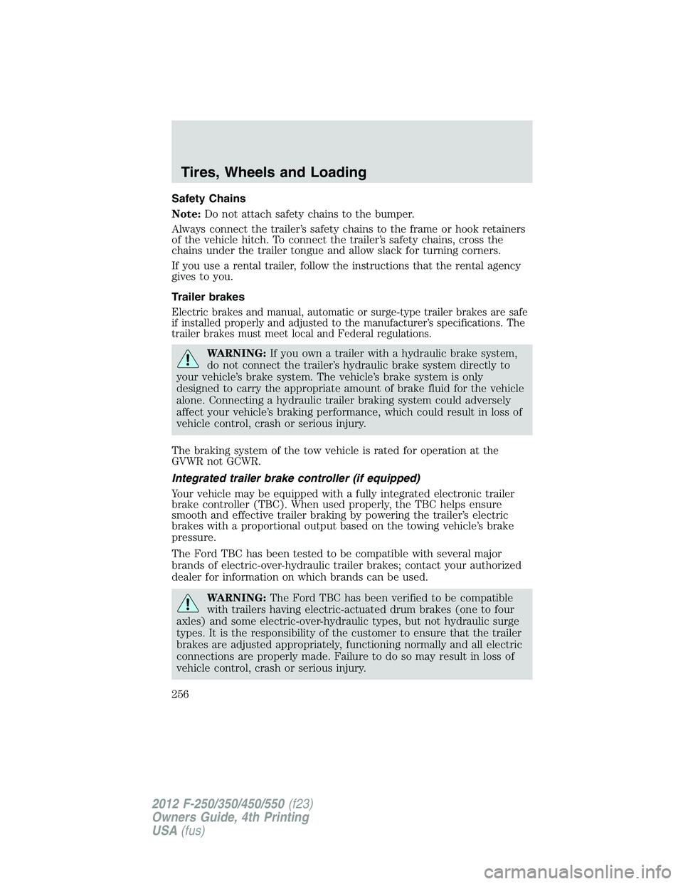
Note: Do not attach safety chains to the bumper.
Always connect the trailer’s safety chains to the frame or hook retainers
of the vehicle hitch. To connect the trailer’s safety chains, cross the
chains under the trailer tongue and allow slack for turning corners.
If you use a rental trailer, follow the instructions that the rental agency
gives to you.
Trailer brakes
Electric brakes and manual, automatic or surge-type trailer brakes are safe
if installed properly and adjusted to the manufacturer’s specifications. The
trailer brakes must meet local and Federal regulations.
WARNING: If you own a trailer with a hydraulic brake system,
do not connect the trailer’s hydraulic brake system directly to
your vehicle’s brake system. The vehicle’s brake system is only
designed to carry the appropriate amount of brake fluid for the vehicle
alone. Connecting a hydraulic trailer braking system could adversely
affect your vehicle’s braking performance, which could result in loss of
vehicle control, crash or serious injury.
The braking system of the tow vehicle is rated for operation at the
GVWR not GCWR.
Integrated trailer brake controller (if equipped)
Your vehicle may be equipped with a fully integrated electronic trailer
brake controller (TBC). When used properly, the TBC helps ensure
smooth and effective trailer braking by powering the trailer’s electric
brakes with a proportional output based on the towing vehicle’s brake
pressure.
The Ford TBC has been tested to be compatible with several major
brands of electric-over-hydraulic trailer brakes; contact your authorized
dealer for information on which brands can be used.
WARNING: The Ford TBC has been verified to be compatible
with trailers having electric-actuated drum brakes (one to four
axles) and some electric-over-hydraulic types, but not hydraulic surge
types. It is the responsibility of the customer to ensure that the trailer
brakes are adjusted appropriately, functioning normally and all electric
connections are properly made. Failure to do so may result in loss of
vehicle control, crash or serious injury.Tires, Wheels and Loading
256
2012 F-250/350/450/550 (f23)
Owners Guide, 4th Printing
USA (fus)
Page 259 of 448
Explanation of instrument cluster warning messages:
The TBC interacts with the instrument cluster message center to display
the following messages:
TRAILER BRAKE MODULE FAULT: This message is displayed and
accompanied by a single chime, in response to faults sensed by the TBC.
In the event this message is seen, please contact your authorized dealer
as soon as possible for diagnosis and repair. The TBC may still function,
but performance may be degraded.
WIRING FAULT ON TRAILER: This message is displayed when a
Short circuit on the electric brake output wire has occurred. If the
WIRING FAULT ON TRAILER message is displayed and accompanied
by a single chime, with no trailer connected, the problem is with the
vehicle wiring from the TBC to the 7–pin connector at the bumper. If the
message is only displayed with a trailer connected, the problem is related
to the trailer wiring; consult your trailer dealer for assistance. This can
be a short to ground (i.e., chaffed wire) or a short to voltage (i.e., pulled
pin on trailer emergency break-away battery) or trailer brakes drawing
too much current.
Note: Your TBC can be diagnosed by your authorized dealer to
determine exactly which trailer fault has occurred; however, if the fault
is with the trailer this diagnosis is not covered under your Ford
warranty.
Points to Remember:
• Remember to adjust gain setting before using the TBC for the first
time.
• Readjust gain setting on the TBC (according to procedure above)
whenever road, weather and trailer or vehicle loading conditions
change from those that existed when the gain was initially set.
• The sliding lever on the TBC should be used only for manual
activation of trailer brakes to assist with proper adjustment of the
GAIN. Misuse, such as application during trailer sway, could cause
instability of trailer and/or tow vehicle.
• Avoid towing in adverse weather conditions. The TBC does not
provide anti-lock control of the trailer wheels. Trailer wheels can lock
up on slippery surfaces, resulting in reduced stability of trailer and
tow vehicle.
• The TBC is equipped with a feature which reduces output at vehicle
speeds below 11 mph (18 km/h) so trailer and vehicle braking is not
jerky or harsh. This feature is only available when applying the brakes
using the vehicle’s brake pedal, not the TBC. Tires, Wheels and Loading
259
2012 F-250/350/450/550 (f23)
Owners Guide, 4th Printing
USA (fus)
Page 263 of 448
RECREATIONAL TOWING
Follow these guidelines if you have a need for recreational (RV) towing.
An example of recreational towing would be towing your vehicle behind
a motor home.
Note: Put your climate control system in recirculated air mode to
prevent exhaust fumes from entering the vehicle. Refer to the Climate
Controls chapter for more information.
In case of a roadside emergency with a disabled vehicle, see Wrecker
towing in the Roadside Emergencies chapter.
These guidelines are designed to ensure that your transmission is not
damaged after the vehicle is hooked-up to the RV or tow dolly.
Drivetrain
configuration Requirements for neutral towing
4x4 with manual-shift
transfer case Transmission in N (Neutral); transfer case in N
(Neutral); hublocks set to FREE*
4x2 or 4x4 with
electronic-shift
transfer case Do not tow your vehicle with any wheels on
the ground, as vehicle or transmission damage
may occur. It is recommended to tow your
vehicle with all four (4) wheels off the ground
such as when using a car-hauling trailer.
Otherwise, no recreational towing is permitted.
*Always make sure that both hub locks are set to the same position.
RECOVERY HOOKS
WARNING: Using recovery hooks is dangerous and should only
be done by a person familiar with proper vehicle recovery safety
practices. Improper use of recovery hooks may cause hook failure
and/or separation from the vehicle and could result in serious injury or
death.
WARNING: Always slowly remove the slack from the recovery
strap prior to pulling. Failure to do so can introduce significantly
higher loads which can cause the recovery hooks to break off, or the
recovery strap to fail which can cause serious injury or death. Tires, Wheels and Loading
263
2012 F-250/350/450/550 (f23)
Owners Guide, 4th Printing
USA (fus)
Page 264 of 448
WARNING: Never link two straps together with a clevis pin.
These heavy metal objects could become projectiles if the strap
breaks and can cause serious injury or death.
Your vehicle comes equipped with frame-mounted front recovery hooks.
These hooks should never have a load applied to them greater than the
GVWR of your vehicle.
Before using the recovery hooks:
• Make sure all attaching points are secure and capable of withstanding
the applied load.
• Never use chains, cables or tow straps with metal hook ends.
• Only use recovery straps that have a minimum breaking strength two
to three times the GVW of the stuck vehicle.
• Make sure the recovery strap is in good condition and free of visible
cuts, tears or damage.
• Use a damper device such as a tarp, heavy blanket or piece of carpet
draped over the recovery strap to help absorb the energy in the event
the strap breaks.
• Make sure the stuck vehicle is not loaded in excess of its GVWR
specified on the certification label.
• Always align the tow vehicle and stuck vehicle in a straight line
(within 10 degrees).
• Keep bystanders to the sides of the vehicle, at a distance of at least
twice the length of the recovery strap. This helps avoid injury from
the hazard of a recovery hook or strap breaking, or a vehicle lurching
into their path.Tires, Wheels and Loading
264
2012 F-250/350/450/550 (f23)
Owners Guide, 4th Printing
USA (fus)
Page 265 of 448

STARTING
Positions of the ignition
1. Off— shuts off the engine and all
accessories/locks the steering wheel
and allows key removal. Note: In
order to switch off the engine while
the vehicle is in motion, shift to
neutral and use the brakes to bring
the vehicle to a safe stop. After the
vehicle has stopped, turn the engine
off and shift into park. Then, turn
the key to the accessory or off
position.
2. Accessory— allows the electrical accessories such as the radio to
operate while the engine is not running. This position also unlocks the
steering wheel.
3. On— all electrical circuits operational. Warning lights illuminated. Key
position when driving.
4. Start— cranks the engine. Release the key as soon as the engine
begins cranking.
Note: Do not store the key in the ignition after the vehicle is turned off
and you have left the vehicle. This could cause a drain on the battery.
Preparing to start your vehicle
Engine starting is controlled by the powertrain control system.
The powertrain control system meets all Canadian interference-causing
equipment standard requirements regulating the impulse electrical field
strength of radio noise.
When starting a fuel-injected engine, don’t press the accelerator before
or during starting. Only use the accelerator when you have difficulty
starting the engine. For more information on starting the vehicle, refer to
Starting the engine in this chapter.
WARNING: Extended idling at high engine speeds can produce
very high temperatures in the engine and exhaust system,
creating the risk of fire or other damage. Driving
265
2012 F-250/350/450/550 (f23)
Owners Guide, 4th Printing
USA (fus)