2012 FIAT IDEA ECU
[x] Cancel search: ECUPage 40 of 210

39
SAFETY
DEVICES
CORRECT USE
OF THE CAR
WARNING
LIGHTS AND
MESSAGES
IN AN
EMERGENCY
CAR
MAINTENANCE
TECHNICAL
SPECIFICATIONS
INDEX
DASHBOARD
AND CONTROLS
Back rest angle adjustment fig. 45
Use lever Aor lever Bto adjust the re-
quired back rest section, then release the
lever.
Central seat back rest adjustment
from inside the car
To set the central seat back rest in hori-
zontal position:
❒operate lever D-fig. 47(one per side)
❒lower the central seat back rest down
completely
❒release the lever.With central seat back rest completely
lowered on the cushion and relevant head
restraint removed (as shown in the figure),
it is possible to use the glass holder A-
fig. 46(where provided).
To bring the central back rest back to ver-
tical position: use again lever D-fig. 47
(one per side) and set it in line with rear
side seat backs, until the securing clip E
locks into place.
fig. 45F0H0049mfig. 46F0H0051mfig. 47F0H0050m
After adjustments, always
check that the seat is firmly
locked in the runners.
WARNING
Once you have released the
lever, check that the seat is
firmly locked in the runners by trying
to move it back and forth. Failure to
lock the seat in place could result in
the seat moving suddenly.
WARNING
Ski tunnel fig. 48
To use the ski tunnel, the armrest shall be
lowered down completely.
It can be used to carry long objects (e.g.:
skis), fitting them into the tunnel from the
boot.
To access the ski tunnel B, lower the rear
central back rest A(as previously de-
scribed).
fig. 48F0H0249m
036-092 idea GB 1 ed 10-07-2008 16:12 Pagina 39
Page 105 of 210

104
CORRECT USE
OF THE CAR
WARNING
LIGHTS AND
MESSAGES
IN AN
EMERGENCY
CAR
MAINTENANCE
TECHNICAL
SPECIFICATIONS
INDEX
DASHBOARD
AND CONTROL
SAFETY
DEVICES
fig. 15F0H0140m
Fit the child seat when the
car is stationary. The child
seat is correctly anchored to the
brackets when you hear the click. Fol-
low the instructions for assembly, dis-
assembly and positioning that the
manufacturer must supply with the
child seat.
WARNING
fig. 14F0H0019m
As the attachment system is different, the
child seat must be secured using the low-
er metal rings A-fig. 15positioned be-
tween the backrest and rear bag. Then, fit
the upper belt (provided with the child
seat) in the supplied ring D-fig. 16locat-
ed at the back of the backrest near the
child seat.
fig. 16F0H0143m
Remember that only Universal Isofix child
seats bearing the type-approval text “ECE
R44/03 Universal Isofix” can be used.
Universal Isofix “Duo Plus” child seat is
available from Lineaccessori Fiat.
For further details about the installa-
tion/use of child seats, refer to the “In-
structions Manual” of the child seat.
093-110 idea GB 1 ed 10-07-2008 8:28 Pagina 104
Page 119 of 210

118
WARNING
LIGHTS AND
MESSAGES
IN AN
EMERGENCY
CAR
MAINTENANCE
TECHNICAL
SPECIFICATIONS
INDEX
DASHBOARD
AND CONTROLS
SAFETY
DEVICES
CORRECT USE
OF THE CAR
Do not exceed the speed limits of the
country you are driving in. In any case do
not exceed 100 km/h.
The ABS system with which
the car may be fitted does
not control the trailer braking system.
Great care should therefore be taken
when driving on slippery road sur-
faces.
Under no circumstances
should the vehicle brake sys-
tem be altered to control the trailer
brake. The trailer braking system
must be fully independent of the ve-
hicle’s hydraulic system.
WARNING
WARNING
INSTALLING THE TOW HOOK
The towing device should be fastened to
the body by specialised personnel ac-
cording to any additional and/or integra-
tive information supplied by the Manufac-
turer of the device.
The towing device must meet current reg-
ulations with reference to 94/20/EC Di-
rective and subsequent amendments.
For any version the towing device used
must match the towable weight of the ve-
hicle on which it is to be installed.
For the electric connection a unified con-
nector should be used which is generally
placed on a special bracket normally fas-
tened to the towing device, and a special
ECU for external trailer light control shall
be installed on the car. For the electrical connection 7 or 13 pins
12VDC connection is to be used (CU-
NA/UNI and ISO/DIN Standards). Follow
the instructions provided by the car man-
ufacturer and/or the tow hitch manufac-
turer.
An electric brake should be supplied di-
rectly by the battery through a cable with
a cross section of no less than 2.5 mm
2.
IMPORTANT Electric brake or other de-
vice shall be used with running engine.
In addition to the electrical branches, the
car’s electric system can only be con-
nected to the supply cable for an electric
brake and to the cable for an internal light,
though not above 15W.
For connections use a preset control unit
with battery cable no less than 2.5 mm
2.
111-122 idea GB 1 ed 10-07-2008 8:29 Pagina 118
Page 145 of 210

144
CAR
MAINTENANCE
TECHNICAL
SPECIFICATIONS
INDEX
DASHBOARD
AND CONTROLS
SAFETY
DEVICES
CORRECT USE
OF THE CAR
WARNING
LIGHTS AND
MESSAGES
IN AN
EMERGENCY
WHEN NEEDING TO
CHANGE A BULB
GENERAL INSTRUCTIONS
❒When a light is not working, check
that it has not fused before changing
the bulb. For the location of the fuses,
refer to “If a fuse blows” in this chap-
ter;
❒Before replacing a bulb that does not
work, check that the contacts are not
oxidised;
❒Burnt bulbs must be replaced by oth-
ers of the same type and power;
❒Always check the height of the head-
light beam after changing a bulb. For versions with alloy rims
❒Make sure that hub contact surfaces
are clean;
❒Refit the standard wheel fitting it on
the pins, refit the fastening bolts and
tighten them using the wrench pro-
vided;
❒Lower the car and remove the jack;
❒Using the wrench provided, tighten
the bolts in the sequence shown pre-
viously for the space-saver spare
wheel fig. 16;
❒Refit the snap-fitted wheel hub cap.
When you have finished
❒Stow the spare wheel C-fig. 11in the
space provided in the boot;
❒Insert the jack partially open in its con-
tainer B-fig. 11forcing it lightly to
prevent it from vibrating when trav-
elling;
❒Put the tools back into their places in
the container;
❒Stow the container complete with
tools on the spare wheel and secure
everything with the clamping device
A-fig. 11;
❒Correctly re-position the stiff cover.
Modifications or repairs to
the electrical system carried
out incorrectly and without bearing
the features of the system in mind can
cause malfunctions with the risk of
fire.
WARNING
Halogen bulbs contain pres-
surised gas which, if broken,
may cause small fragments of glass to
be projected outwards.
WARNING
Only touch the metal part
when handling halogen bulbs.
If the transparent bulb is
touched it reduces the intesi-
ty of the light emitted and can also re-
duce the life of the bulb. If you touch
the bulb accidentally, rub it with a
cloth moistened with alcohol and leave
it to dry.
IMPORTANT The headlight inner surface
may be lightly misted over: this is not a
fault but a natural fact due to low tem-
perature and the level of air humidity. It
will disappear as soon the headlights are
turned on. The presence of drops inside
the headlights means water infiltration,
therefore contact Fiat Dealership.
133-160 idea GB 1 ed 10-07-2008 8:30 Pagina 144
Page 149 of 210

148
CAR
MAINTENANCE
TECHNICAL
SPECIFICATIONS
INDEX
DASHBOARD
AND CONTROLS
SAFETY
DEVICES
CORRECT USE
OF THE CAR
WARNING
LIGHTS AND
MESSAGES
IN AN
EMERGENCY
fig. 20F0H0181mfig. 21
C
B
D
F0H0214m
fig. 22F0H0182m
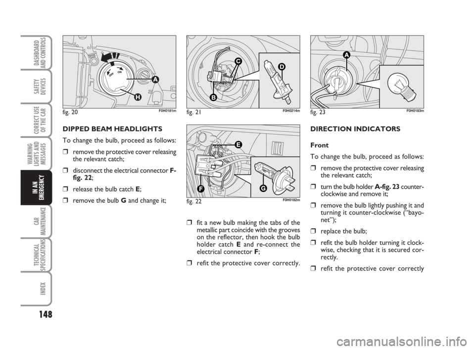
DIPPED BEAM HEADLIGHTS
To change the bulb, proceed as follows:
❒remove the protective cover releasing
the relevant catch;
❒disconnect the electrical connector F-
fig. 22;
❒release the bulb catch E;
❒remove the bulb Gand change it;
fig. 23F0H0183m
DIRECTION INDICATORS
Front
To change the bulb, proceed as follows:
❒remove the protective cover releasing
the relevant catch;
❒turn the bulb holder A-fig. 23counter-
clockwise and remove it;
❒remove the bulb lightly pushing it and
turning it counter-clockwise (“bayo-
net”);
❒replace the bulb;
❒refit the bulb holder turning it clock-
wise, checking that it is secured cor-
rectly.
❒refit the protective cover correctly
❒fit a new bulb making the tabs of the
metallic part coincide with the grooves
on the reflector, then hook the bulb
holder catch Eand re-connect the
electrical connector F;
❒refit the protective cover correctly.
133-160 idea GB 1 ed 10-07-2008 8:30 Pagina 148