Page 152 of 210

151
CAR
MAINTENANCE
TECHNICAL
SPECIFICATIONS
INDEX
DASHBOARD
AND CONTROLS
SAFETY
DEVICES
CORRECT USE
OF THE CAR
WARNING
LIGHTS AND
MESSAGES
IN AN
EMERGENCY
The bulbs are arranged inside the light unit
as follows:
D: sidelights / STOP
E: direction indicators
F: reversing light
G: rear fog lights
fig. 29F0H0189mfig. 30F0H0190m
ADDITIONAL BRAKING LIGHT
(THIRD STOP)
To change the bulbs, proceed as follows:
❒open the tailgate;
❒slacken the two fastening screws A-
fig. 30;
❒press the catch Band remove the bulb
holder;
❒remove the snap-fitted bulbs and
change them;
❒insert the bulb holder making sure the
catch Bclicks into place; drive in the
two fastening screws A.
IMPORTANT Where provided, on ver-
sions with dark windows, replace the
whole light unit since it is sealed.Number plate light
To change the bulb, proceed as follows:
❒work in the point shown by the arrow
and remove the transparent A-fig. 31;
❒change the bulb Breleasing it from the
side contacts and making sure the new
bulb is correctly fastened between the
contacts;
❒refit the transparent.
fig. 31F0H0192m
133-160 idea GB 1 ed 10-07-2008 8:30 Pagina 151
Page 153 of 210

152
CAR
MAINTENANCE
TECHNICAL
SPECIFICATIONS
INDEX
DASHBOARD
AND CONTROLS
SAFETY
DEVICES
CORRECT USE
OF THE CAR
WARNING
LIGHTS AND
MESSAGES
IN AN
EMERGENCY
IF AN INTERIOR LIGHT
BURNS OUT
For the type of bulb and power rating, see
“When needing to change a bulb”.
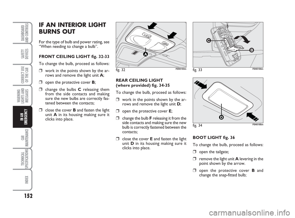
FRONT CEILING LIGHT fig. 32-33
To change the bulb, proceed as follows:
❒work in the points shown by the ar-
rows and remove the light unit A;
❒open the protective cover B;
❒change the bulbs Creleasing them
from the side contacts and making
sure the new bulbs are correctly fas-
tened between the contacts;
❒close the cover Band fasten the light
unit Ain its housing making sure it
clicks into place. REAR CEILING LIGHT
(where provided) fig. 34-35
To change the bulb, proceed as follows:
❒work in the points shown by the ar-
rows and remove the light unit D;
❒open the protective cover E;
❒change the bulb Freleasing it from the
side contacts and making sure the new
bulb is correctly fastened between the
contacts;
❒close the cover Eand fasten the light
unit Din its housing making sure it
clicks into place.
fig. 32F0H0193mfig. 33F0H0194m
fig. 34F0H0195m
BOOT LIGHT fig. 36
To change the bulb, proceed as follows:
❒open the tailgate;
❒remove the light unit Alevering in the
point shown by the arrow.
❒open the protective cover Band
change the snap-fitted bulb;
133-160 idea GB 1 ed 10-07-2008 8:30 Pagina 152
Page 178 of 210

177
TECHNICAL
SPECIFICATIONS
INDEX
DASHBOARD
AND CONTROLS
SAFETY
DEVICES
CORRECT USE
OF THE CAR
WARNING
LIGHTS AND
MESSAGES
IN AN
EMERGENCY
CAR
MAINTENANCE
fig. 14F0H0217mfig. 15F0H0218m
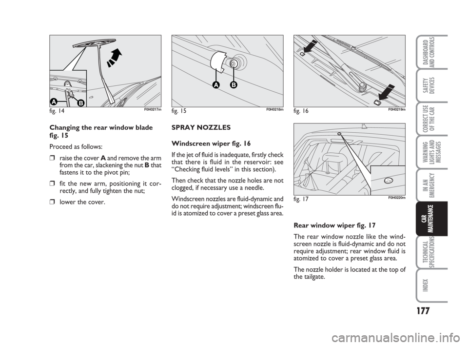
Changing the rear window blade
fig. 15
Proceed as follows:
❒raise the cover Aand remove the arm
from the car, slackening the nut Bthat
fastens it to the pivot pin;
❒fit the new arm, positioning it cor-
rectly, and fully tighten the nut;
❒lower the cover.SPRAY NOZZLES
Windscreen wiper fig. 16
If the jet of fluid is inadequate, firstly check
that there is fluid in the reservoir: see
“Checking fluid levels” in this section).
Then check that the nozzle holes are not
clogged, if necessary use a needle.
Windscreen nozzles are fluid-dynamic and
do not require adjustment; windscreen flu-
id is atomized to cover a preset glass area.
fig. 16F0H0219m
fig. 17F0H0220m
Rear window wiper fig. 17
The rear window nozzle like the wind-
screen nozzle is fluid-dynamic and do not
require adjustment; rear window fluid is
atomized to cover a preset glass area.
The nozzle holder is located at the top of
the tailgate.
161-180 idea GB 1 ed 10-07-2008 8:30 Pagina 177