2012 FIAT IDEA low beam
[x] Cancel search: low beamPage 133 of 210

132
IN AN
EMERGENCY
CAR
MAINTENANCE
TECHNICAL
SPECIFICATIONS
INDEX
DASHBOARD
AND CONTROLS
SAFETY
DEVICES
CORRECT USE
OF THE CAR
WARNING
LIGHTS AND
MESSAGES
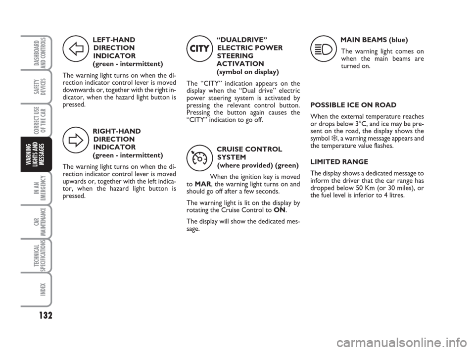
LEFT-HAND
DIRECTION
INDICATOR
(green - intermittent)
The warning light turns on when the di-
rection indicator control lever is moved
downwards or, together with the right in-
dicator, when the hazard light button is
pressed.
F
RIGHT-HAND
DIRECTION
INDICATOR
(green - intermittent)
The warning light turns on when the di-
rection indicator control lever is moved
upwards or, together with the left indica-
tor, when the hazard light button is
pressed.
D
“DUALDRIVE”
ELECTRIC POWER
STEERING
ACTIVATION
(symbol on display)
The “CITY” indication appears on the
display when the “Dual drive” electric
power steering system is activated by
pressing the relevant control button.
Pressing the button again causes the
“CITY” indication to go off.
CITY
CRUISE CONTROL
SYSTEM
(where provided) (green)
When the ignition key is moved
to MAR, the warning light turns on and
should go off after a few seconds.
The warning light is lit on the display by
rotating the Cruise Control to ON.
The display will show the dedicated mes-
sage.
Ü
MAIN BEAMS (blue)
The warning light comes on
when the main beams are
turned on.
1
POSSIBLE ICE ON ROAD
When the external temperature reaches
or drops below 3°C, and ice may be pre-
sent on the road, the display shows the
symbol
❄, a warning message appears and
the temperature value flashes.
LIMITED RANGE
The display shows a dedicated message to
inform the driver that the car range has
dropped below 50 Km (or 30 miles), or
the fuel level is inferior to 4 litres.
123-132 idea GB 1 ed 10-07-2008 8:29 Pagina 132
Page 145 of 210

144
CAR
MAINTENANCE
TECHNICAL
SPECIFICATIONS
INDEX
DASHBOARD
AND CONTROLS
SAFETY
DEVICES
CORRECT USE
OF THE CAR
WARNING
LIGHTS AND
MESSAGES
IN AN
EMERGENCY
WHEN NEEDING TO
CHANGE A BULB
GENERAL INSTRUCTIONS
❒When a light is not working, check
that it has not fused before changing
the bulb. For the location of the fuses,
refer to “If a fuse blows” in this chap-
ter;
❒Before replacing a bulb that does not
work, check that the contacts are not
oxidised;
❒Burnt bulbs must be replaced by oth-
ers of the same type and power;
❒Always check the height of the head-
light beam after changing a bulb. For versions with alloy rims
❒Make sure that hub contact surfaces
are clean;
❒Refit the standard wheel fitting it on
the pins, refit the fastening bolts and
tighten them using the wrench pro-
vided;
❒Lower the car and remove the jack;
❒Using the wrench provided, tighten
the bolts in the sequence shown pre-
viously for the space-saver spare
wheel fig. 16;
❒Refit the snap-fitted wheel hub cap.
When you have finished
❒Stow the spare wheel C-fig. 11in the
space provided in the boot;
❒Insert the jack partially open in its con-
tainer B-fig. 11forcing it lightly to
prevent it from vibrating when trav-
elling;
❒Put the tools back into their places in
the container;
❒Stow the container complete with
tools on the spare wheel and secure
everything with the clamping device
A-fig. 11;
❒Correctly re-position the stiff cover.
Modifications or repairs to
the electrical system carried
out incorrectly and without bearing
the features of the system in mind can
cause malfunctions with the risk of
fire.
WARNING
Halogen bulbs contain pres-
surised gas which, if broken,
may cause small fragments of glass to
be projected outwards.
WARNING
Only touch the metal part
when handling halogen bulbs.
If the transparent bulb is
touched it reduces the intesi-
ty of the light emitted and can also re-
duce the life of the bulb. If you touch
the bulb accidentally, rub it with a
cloth moistened with alcohol and leave
it to dry.
IMPORTANT The headlight inner surface
may be lightly misted over: this is not a
fault but a natural fact due to low tem-
perature and the level of air humidity. It
will disappear as soon the headlights are
turned on. The presence of drops inside
the headlights means water infiltration,
therefore contact Fiat Dealership.
133-160 idea GB 1 ed 10-07-2008 8:30 Pagina 144
Page 148 of 210

147
CAR
MAINTENANCE
TECHNICAL
SPECIFICATIONS
INDEX
DASHBOARD
AND CONTROLS
SAFETY
DEVICES
CORRECT USE
OF THE CAR
WARNING
LIGHTS AND
MESSAGES
IN AN
EMERGENCY
IF AN EXTERIOR LIGHT
BURNS OUT
For the type of bulb and power rating, see
“When needing to change a bulb”.
FRONT LIGHT UNITS
The front light units contain the sidelights,
the dipped beam, main beam, direction in-
dicator and fog light bulbs.
To change the bulbs of the sidelights, low
beams, direction indicators and fog lights
it is necessary to remove the cover A-
fig. 18releasing the catch B.
fig. 18F0H0179mfig. 19F0H0180m
The bulbs are arranged inside the light unit
fig. 19 as follows:
G: direction indicators
F: main beam headlights
E: sidelights
D: fog lights
C: dipped beam headlights
After replacement, refit the covers cor-
rectly checking that they are properly se-
cured.MAIN BEAM HEADLIGHTS
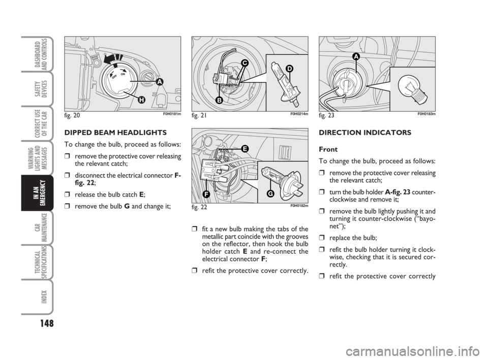
To change the bulb, proceed as follows:
❒turn the cap A-fig. 20anticlockwise
and remove it;
❒disconnect the electrical connector B-
fig. 21;
❒release the bulb catch C-fig. 21;
❒remove the bulb D-fig. 21and change
it;
❒refit the catch C-fig. 21, connect the
electrical connector Band fit the cap
A-fig. 20turning it clockwise. Put the
cap ventilation outlet H-fig. 20from
the top downwards.
133-160 idea GB 1 ed 10-07-2008 8:30 Pagina 147
Page 149 of 210

148
CAR
MAINTENANCE
TECHNICAL
SPECIFICATIONS
INDEX
DASHBOARD
AND CONTROLS
SAFETY
DEVICES
CORRECT USE
OF THE CAR
WARNING
LIGHTS AND
MESSAGES
IN AN
EMERGENCY
fig. 20F0H0181mfig. 21
C
B
D
F0H0214m
fig. 22F0H0182m
DIPPED BEAM HEADLIGHTS
To change the bulb, proceed as follows:
❒remove the protective cover releasing
the relevant catch;
❒disconnect the electrical connector F-
fig. 22;
❒release the bulb catch E;
❒remove the bulb Gand change it;
fig. 23F0H0183m
DIRECTION INDICATORS
Front
To change the bulb, proceed as follows:
❒remove the protective cover releasing
the relevant catch;
❒turn the bulb holder A-fig. 23counter-
clockwise and remove it;
❒remove the bulb lightly pushing it and
turning it counter-clockwise (“bayo-
net”);
❒replace the bulb;
❒refit the bulb holder turning it clock-
wise, checking that it is secured cor-
rectly.
❒refit the protective cover correctly
❒fit a new bulb making the tabs of the
metallic part coincide with the grooves
on the reflector, then hook the bulb
holder catch Eand re-connect the
electrical connector F;
❒refit the protective cover correctly.
133-160 idea GB 1 ed 10-07-2008 8:30 Pagina 148
Page 202 of 210

201
SAFETY
DEVICES
CORRECT USE
OF THE CAR
WARNING
LIGHTS AND
MESSAGES
IN AN
EMERGENCY
CAR
MAINTENANCE
TECHNICAL
SPECIFICATIONS
DASHBOARD
AND CONTROLS
INDEX
Dipped beam headlights
– bulb replacement ................. 148
– control .................................. 59
Direction indicators ................. 59
– bulb replacement ................. 148
– control .................................. 59
Door pockets ............................. 69
Doors ........................................ 17-134
Emergency device for locking
doors from the outside ...... 17-134
Dualdrive
(electric power steering) ...... 87
EBD (electronic brake force
distributor) ................................. 83
Emergency device for locking
doors from the outside ......... 17
Engine
– fuel feed ................................. 187
– identification code ............... 184
– injection/ignition ................. 187– technical data ....................... 185
Engine coolant gauge................. 19
Engine coolant level ................ 170
Engine oil
– checking level........................ 169
– consumption ......................... 169
– technical specifications ....... 195
EOBD (system) ......................... 84
External lights ............................. 58
Fiat CODE (system) ............... 9
Fix &Go (tyre repair kit) ......... 136
Flashing the headlights ............. 58
Fluids and lubricants ................ 196
Follow me home (device) ....... 59
FPS (fuel cut-off switch) .......... 67
Front fog lights
– bulb replacement ................. 149
– control button ...................... 66Fuel
– consumption ......................... 198
– fuel cut-off switch ................ 67
– level gauge ............................ 19
Fuel cut-off switch ..................... 67
Fuel filler cap............................... 91
Fuses ............................................. 153
Gearbox (use). .......................... 115
Glass/can holders ....................... 69
Handbrake ................................. 114
Hazard lights
– control .................................. 66
Head restraints ......................... 41
Headlights ................................... 82
(electric adjusting device) ..... 82
Heated rear window ............... 44
Heating and ventilation............. 45
Identification data .................... 182
Ignition switch ........................... 18
200-208 idea GB 1 ed 10-07-2008 10:58 Pagina 201