2012 FIAT FREEMONT remote start
[x] Cancel search: remote startPage 156 of 332
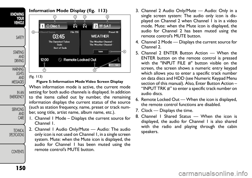
Information Mode Display (fig. 113)
When information mode is active, the current mode
setting for both audio channels is displayed. In addition
to the items called out by number, the remaining
information displays the current status of the source
(such as station frequency, name, preset or track num-
ber, song title, artist name, album name, etc.).
1. Channel 1 Mode – Displays the current source forChannel 1.
2. Channel 1 Audio Only/Mute — Audio: The audio only icon is not used on Channel 1, in a single screen
system. Mute: when the Mute icon is displayed, the
audio for Channel 1 has been muted using the
remote control’s MUTE button. 3. Channel 2 Audio Only/Mute — Audio: Only in a
single screen system: The audio only icon is dis-
played on Channel 2 when Channel 1 is in a video
mode. Mute: when the Mute icon is displayed, the
audio for Channel 2 has been muted using the
remote control’s MUTE button.
4. Channel 2 Mode — Displays the current source for Channel 2.
5. Channel 2 ENTER Button Action — When the ENTER button on the remote control is pressed
with the "INPUT FILE #" button visible on the
screen, the screen shows a numeric entry keypad
which allows you to enter a specific track number
on data discs and HDD (see Numeric Keypad Menu
section of this manual). Also, Enter Button Action –
“INPUT TRK #” to enter a specific track number on
audio discs.
6. Remote Locked Out — When the icon is displayed, the remote control functions are disabled.
7. Clock — Displays the time.
8. Channel 1 Shared Status — When the icon is displayed, the audio for Channel 1 is also shared
with the radio and playing through the cabin
speakers.(fig. 113) Figure 5: Information Mode Video Screen Display
150
KNOWING YOUR
VEHICLE
SAFETY
STARTING AND
DRIVING
WARNING LIGHTSAND
MESSAGES
IN AN
EMERGENCY
SERVICING AND
CARETECHNICAL
SPECIFICATIONSCONTENTS
Page 157 of 332
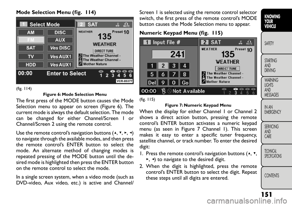
Mode Selection Menu (fig. 114)
The first press of the MODE button causes the Mode
Selection menu to appear on screen (Figure 6). The
current mode is always the default selection. The mode
can be changed for either Channel/Screen 1 or
Channel/Screen 2 using the remote control.
Use the remote control’s navigation buttons (▴,▾ ,▸ ,◂ )
to navigate through the available modes, and then press
the remote control’s ENTER button to select the
mode. An alternate method of changing modes is
repeated pressing of the MODE button until the de-
sired mode is highlighted then press the ENTER button
on the remote control to select the mode.
In a single screen system, when a video mode (such as
DVD-video, Aux video, etc.) is active and Channel/ Screen 1 is selected using the remote control selector
switch, the first press of the remote control’s MODE
button causes the Mode Selection menu to appear.
Numeric Keypad Menu (fig. 115)
When the display for either Channel 1 or Channel 2
shows a direct action button, pressing the remote
control’s ENTER button activates a numeric keypad
menu (as seen in Figure 7 Channel 1). This screen
makes it easy to enter a specific tuner frequency,
satellite channel, or track number. To enter the desireddigit:
1. Press the remote control’s navigation buttons (
▴,▾ ,
▸ ,◂ ) to navigate to the desired digit.
2. When the digit is highlighted, press the remote control’s ENTER button to select the digit. Repeat
these steps until all digits are entered.(fig. 114)
Figure 6: Mode Selection Menu
(fig. 115)Figure 7: Numeric Keypad Menu
151
KNOWING
YOURVEHICLESAFETY
STARTING ANDDRIVING
WARNING LIGHTSAND
MESSAGES
IN AN
EMERGENCY
SERVICING AND
CARETECHNICAL
SPECIFICATIONSCONTENTS
Page 158 of 332
3. To delete the last digit, navigate to the Del buttonand press the remote control’s ENTER button.
4. After all of the digits are entered, navigate to the Go button and press the remote control’s ENTER
button.
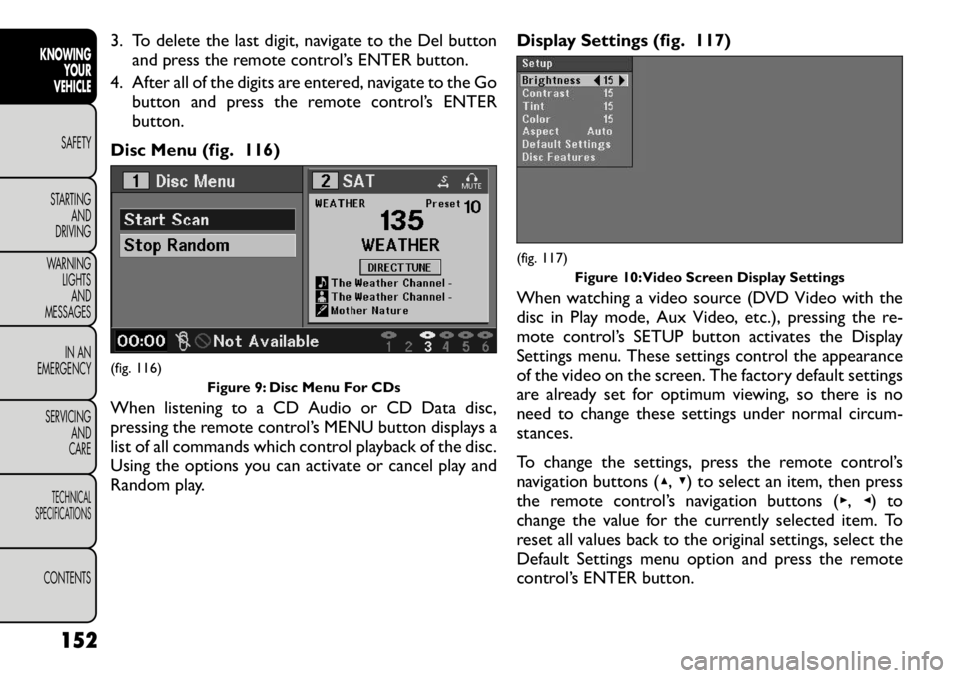
Disc Menu (fig. 116)
When listening to a CD Audio or CD Data disc,
pressing the remote control’s MENU button displays a
list of all commands which control playback of the disc.
Using the options you can activate or cancel play and
Random play. Display Settings (fig. 117)
When watching a video source (DVD Video with the
disc in Play mode, Aux Video, etc.), pressing the re-
mote control’s SETUP button activates the Display
Settings menu. These settings control the appearance
of the video on the screen. The factory default settings
are already set for optimum viewing, so there is no
need to change these settings under normal circum-
stances.
To change the settings, press the remote control’s
navigation buttons (
▴,▾ ) to select an item, then press
the remote control’s navigation buttons ( ▸, ◂) to
change the value for the currently selected item. To
reset all values back to the original settings, select the
Default Settings menu option and press the remote
control’s ENTER button.(fig. 116) Figure 9: Disc Menu For CDs
(fig. 117)Figure 10:Video Screen Display Settings
152
KNOWING YOUR
VEHICLE
SAFETY
STARTING AND
DRIVING
WARNING LIGHTSAND
MESSAGES
IN AN
EMERGENCY
SERVICING AND
CARETECHNICAL
SPECIFICATIONSCONTENTS
Page 159 of 332
Disc Features control the remote DVD player's (for
versions/markets, where provided) settings of DVD
being watched in the remote player.
Listening To Audio With The Screen Closed
To listen to only audio portion of the channel with the
screen closed:
• Set the audio to the desired source and channel.
• Close the video screen.
• To change the current audio mode, press the remotecontrol’s MODE button. This will automatically se-
lect the next available audio mode without using the
Mode Select menu.
• When the screen is reopened, the video screen will automatically turn back on and show the appropriate
display menu or media.
If the screen is closed and there is no audio heard,
verify that the headphones are turned on (the ON
indicator is illuminated) and the headphone selector
switch is on the desired channel. If the headphones are
turned on, press the remote control’s power button to
turn audio on. If audio is still not heard, check that fully
charged batteries are installed in the headphones. Why Does The Screen Mode Change
Automatically?
In order to make the operation of the VES™ simple
and with the least amount of driver distraction, specific
events will cause the screen(s) to automatically switch
to DVD mode. These events are:
• Loading a disc in the DVD player (if so equipped),
• Pressing the PLAY button on the DVD player face-
plate when the disc is stopped or paused, or
• AM/FM band selection via Radio.
If your vehicle is not equipped with the separate DVD
player, the following events in the Radio will cause the
screen(s) to automatically switch to Radio Disc mode.
• Loading a disc in the radio CD/DVD player
• AM/FM band selection via Radio
Auxiliary Inputs
For each video screen there is an auxiliary (Aux jack)
device input which is used to connect external audio/
video sources to the VES™. Examples of devices that
can be connected to the Aux inputs include portable
music players, video cameras, VCR’s, game systems,
and other devices with audio and/or video outputs.
The Aux jacks are typically located on the back of the
center console or on one of the vehicles side panels in
the rear occupant area.
153
KNOWING
YOURVEHICLESAFETY
STARTING ANDDRIVING
WARNING LIGHTSAND
MESSAGES
IN AN
EMERGENCY
SERVICING AND
CARETECHNICAL
SPECIFICATIONSCONTENTS
Page 160 of 332
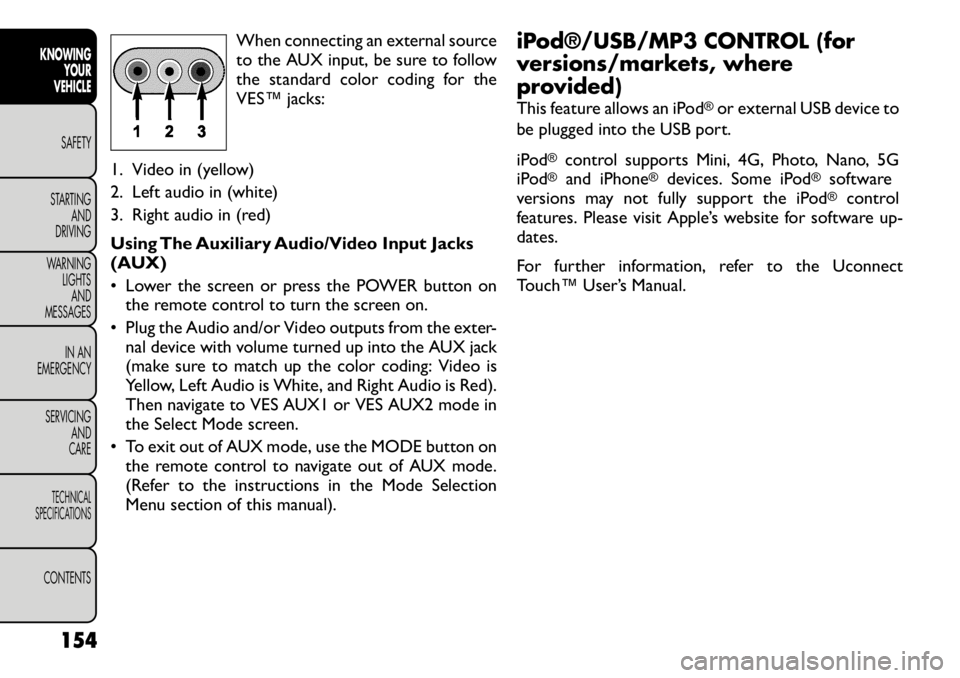
When connecting an external source
to the AUX input, be sure to follow
the standard color coding for the
VES™ jacks:
1. Video in (yellow)
2. Left audio in (white)
3. Right audio in (red)
Using The Auxiliary Audio/Video Input Jacks
(AUX)
• Lower the screen or press the POWER button on the remote control to turn the screen on.
• Plug the Audio and/or Video outputs from the exter- nal device with volume turned up into the AUX jack
(make sure to match up the color coding: Video is
Yellow, Left Audio is White, and Right Audio is Red).
Then navigate to VES AUX1 or VES AUX2 mode in
the Select Mode screen.
• To exit out of AUX mode, use the MODE button on the remote control to navigate out of AUX mode.
(Refer to the instructions in the Mode Selection
Menu section of this manual). iPod®/USB/MP3 CONTROL (for
versions/markets, where
provided)
This feature allows an iPod
®or external USB device to
be plugged into the USB port.
iPod
®
control supports Mini, 4G, Photo, Nano, 5G
iPod
®
and iPhone
®
devices. Some iPod
®
software
versions may not fully support the iPod®
control
features. Please visit Apple’s website for software up-
dates.
For further information, refer to the Uconnect
Touch™ User’s Manual.
154
KNOWING YOUR
VEHICLE
SAFETY
STARTING AND
DRIVING
WARNING LIGHTSAND
MESSAGES
IN AN
EMERGENCY
SERVICING AND
CARETECHNICAL
SPECIFICATIONSCONTENTS
Page 237 of 332

IN AN EMERGENCY
JUMP-STARTING
If your vehicle has a discharged battery, it can be
jump-started using a set of jumper cables and a battery
in another vehicle or by using a portable battery
booster pack. Jump-starting can be dangerous if done
improperly so please follow the procedures in this
section carefully.
NOTE: When using a portable battery booster pack
follow the manufacturer's operating instructions and
precautions.
Do not use a portable battery booster
pack or any other booster source with a
system voltage greater than 12 Volts or
damage to the battery, starter motor, alternator
or electrical system may occur.
WARNING!
Do not attempt jump-starting if the bat-
tery is frozen. It could rupture or explode
and cause personal injury. PREPARATIONS FOR JUMP-START
The battery in your vehicle is located between the left
front headlight assembly and the left front wheel splash
shield. To allow jump-starting, there are remote bat-
tery posts located on the left side of the engine com-
partment. (fig. 153)
(fig. 153)
Remote Battery Posts
1 — Remote Positive (+) Post (Covered With Protective
Cap)
2 — Remote Negative (-) Post
231
KNOWING
YOURVEHICLE SAFETY
STARTING ANDDRIVING
WARNING LIGHTSAND
MESSAGESIN AN
EMERGENCYSERVICING AND
CARETECHNICAL
SPECIFICATIONSCONTENTS
Page 238 of 332

WARNING!
Take care to avoid the radiator cooling
fan whenever the hood is raised. It can
start anytime the ignition switch is ON.You can
be injured by moving fan blades.
Remove any metal jewelry such as watch bands
or bracelets that might make an inadvertent
electrical contact .You could be seriously injured.
Batteries contain sulfuric acid that can burn
your skin or eyes and generate hydrogen gas
which is flammable and explosive. Keep open
flames or sparks away from the battery.
1. Set the parking brake, shift the automatic transmis- sion into PARK and turn the ignition to LOCK.
2. Turn off the heater, radio, and all unnecessary elec- trical accessories.
3. Remove the protective cover over the remote posi- tive (+)battery post. To remove the cover, press
the locking tab and pull upward on the cover.
4. If using another vehicle to jump-start the battery, park the vehicle within the jumper cables reach, set
the parking brake and make sure the ignition is OFF.
WARNING!
Do not allow vehicles to touch each
other as this could establish a ground
connection and personal injury could result .
JUMP-STARTING PROCEDURE
WARNING!
Failure to follow this procedure could
result in personal injury or property
damage due to battery explosion.Failure to follow these procedures could
result in damage to the charging system
of the booster vehicle or the discharged
vehicle.
1. Connect the positive (+)end of the jumper cable to
the remote positive (+)post of the discharged
vehicle.
2. Connect the opposite end of the positive (+)
jumper cable to the positive (+)post of the booster
battery.
3. Connect the negative end (-)of the jumper cable to
the negative (-)post of the booster battery.
4. Connect the opposite end of the negative (-)
jumper cable to the remote negative (-)post of the
vehicle with the discharged battery.
232
KNOWING YOUR
VEHICLE
SAFETY
STARTING AND
DRIVING
WARNING LIGHTSAND
MESSAGES
IN AN
EMERGENCY
SERVICING AND
CARETECHNICAL
SPECIFICATIONSCONTENTS
Page 239 of 332

WARNING!
Do not connect the cable to the negative
post(-)of the discharged battery. The
resulting electrical spark could cause the battery
to explode and could result in personal injury.
5. Start the engine in the vehicle that has the booster battery, let the engine idle a few minutes, and then
start the engine in the vehicle with the discharged
battery.
Once the engine is started, remove the jumper
cables in the reverse sequence:
6. Disconnect the negative (-)jumper cable from the
remote negative (-)post of the vehicle with the
discharged battery.
7. Disconnect the negative end (-)of the jumper cable
from the negative (-)post of the booster battery.
8. Disconnect the opposite end of the positive (+)
jumper cable from the positive (+)post of the
booster battery.
9. Disconnect the positive (+)end of the jumper cable
from the remote positive (+)post of the discharged
vehicle.
10. Reinstall the protective cover over the remote positive (+)battery post of the discharged vehicle. If frequent jump-starting is required to start your
vehicle, you should have the battery and charging
system inspected at your authorized dealer.
Accessories that can be plugged into the
vehicle power outlets draw power from
the vehicle’s battery, even when not in
use (i.e., cellular phones, etc .). Eventually, if
plugged in long enough, the vehicle’s battery will
discharge sufficiently to degrade battery life
and/or prevent the engine from starting.
233
KNOWING
YOURVEHICLE SAFETY
STARTING ANDDRIVING
WARNING LIGHTSAND
MESSAGESIN AN
EMERGENCYSERVICING AND
CARETECHNICAL
SPECIFICATIONSCONTENTS