2012 FIAT 500 ABARTH instrument panel
[x] Cancel search: instrument panelPage 189 of 358
NOTE:
•It is not necessary to move the temperature settings for
cold or hot vehicles. The system automatically adjusts
the temperature, mode and fan speed to provide
comfort as quickly as possible.
•The temperature can be displayed in U.S. or Metric
units by selecting the US/M customer-programmable
feature. Refer to the “Electronic Vehicle Information
Center (EVIC) — Customer-Programmable Features”
in this section of the manual.
To provide you with maximum comfort in the Automatic
mode during cold start-ups, the blower fan will remain
on low until the engine warms up. The blower will
increase in speed and transition into AUTO mode.
Manual Operation
This system offers a full complement of manual override
features. NOTE:
Each of these features operates independently
from each other. If any feature is controlled manually,
temperature control will continue to operate automati-
cally.
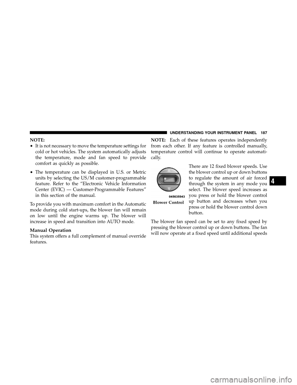
There are 12 fixed blower speeds. Use
the blower control up or down buttons
to regulate the amount of air forced
through the system in any mode you
select. The blower speed increases as
you press or hold the blower control
up button and decreases when you
press or hold the blower control down
button.
The blower fan speed can be set to any fixed speed by
pressing the blower control up or down buttons. The fan
will now operate at a fixed speed until additional speeds
Blower Control
4
UNDERSTANDING YOUR INSTRUMENT PANEL 187
Page 190 of 358
are selected. This allows the front occupants to control
the volume of air circulated in the vehicle and cancel the
AUTO mode.
The operator can also select the direction of the airflow
by selecting one of the following positions.
Panel ModeAir comes from the outlets in the instrument panel.
Each of these outlets can be individually adjusted to
direct the flow of air. The air vanes of the center outlets
and outboard outlets can be moved up and down or side
to side to regulate airflow direction. There is a shut off
wheel located below the air vanes to shut off or adjust the
amount of airflow from these outlets.
Floor Mode Air comes from the floor outlets. A slight amount of
air is directed through the defrost and side window
demister outlets. Bi-Level
Air is directed through the panel and floor outlets.
Press and release the Panel mode button and Floor
mode button to enter Bi-Level mode, the indicators
illuminate when ON. Performing this function will cause
the ATC to switch into manual mode.
Mix Mode Air comes from the floor, defrost and side window
demister outlets. This mode works best in cold or
snowy conditions. It allows you to stay comfortable
while keeping the windshield clear.
Defrost Mode Air comes from the windshield and side window
demister outlets. Use Defrost mode with maximum
temperature settings for best windshield and side win-
dow defrosting. When the defrost mode is selected, the
blower will automatically default to medium-high.
188 UNDERSTANDING YOUR INSTRUMENT PANEL
Page 191 of 358
NOTE:While operating in the other modes, the system
will not automatically sense the presence of fog, mist or
ice on the windshield. Defrost mode must be manually
selected to clear the windshield and side glass.
Air Conditioning (A/C)
The Air Conditioning (A/C) button allows the operator
to manually activate or deactivate the air conditioning
system. When in A/C mode with the ATC set to a cool
temperature, dehumidified air flows through the air
outlets. If Economy mode is desired, press the A/C
button to turn off the A/C mode in the ATC display and
deactivate the A/C system.
NOTE:
•If the system is in Mix or Defrost Mode, the A/C can
be turned off, but the A/C system shall remain active
to prevent fogging of the windows.
•If fog or mist appears on the windshield or side glass,
select Defrost mode and increase blower speed.
Recirculation Control
When outside air contains smoke, odors, or
high humidity, or if rapid cooling is desired,
you may wish to recirculate interior air by
pressing the RECIRCULATION control button.
Recirculation mode should only be used temporarily. The
recirculation LED will illuminate when this button is
selected. Push the button a second time to turn off the
Recirculation mode LED and allow outside air into the
vehicle.
NOTE: In cold weather, use of Recirculation mode may
lead to excessive window fogging. The Recirculation
mode is not allowed in the Defrost mode to improve
window clearing operation. Recirculation will be dis-
abled automatically if this mode is selected.
4
UNDERSTANDING YOUR INSTRUMENT PANEL 189
Page 192 of 358
Operating Tips
Window Fogging
Windows will fog on the inside when the humidity inside
the vehicle is high. This often occurs in mild or cool
temperatures when it’s rainy or humid. In most cases,
turning the air conditioning (pressing the A/C button) on
will clear the fog. Adjust the temperature control, air
direction, and blower speed to maintain comfort.
As the temperature gets colder, it may be necessary to
direct air onto the windshield. Adjust the temperature
control and blower speed to maintain comfort. Higher
blower speeds will reduce fogging. Interior fogging on
the windshield can be quickly removed by selecting the
DEFROST mode.
Regular cleaning of the inside of the windows with a
non-filming cleaning solution (vinegar and water works
very well) will help prevent contaminates (cigarettesmoke, perfumes, etc.) from sticking to the windows.
Contaminates increase the rate of window fogging.Summer Operation
NOTE:
In some cases during high temperature opera-
tion, the air conditioning system performance may be
reduced. This is to help protect the engine from overheat-
ing during the high load condition.
Your air conditioning system is also equipped with an
automatic recirculation system. When the system senses
a heavy load or high heat conditions, it may use Recir-
culation A/C mode to provide additional comfort while
in automatic mode.
Winter Operation
When operating the system during the winter months,
make sure the air intake, located directly in front of the
windshield, is free of ice, slush, snow, or other
obstructions.
190 UNDERSTANDING YOUR INSTRUMENT PANEL
Page 193 of 358
Vacation Storage
Anytime you store your vehicle, or keep it out of service
(i.e., vacation) for two weeks or more, run the air
conditioning system at idle for about five minutes in the
fresh air using the high blower setting. This will ensure
adequate system lubrication to minimize the possibility
of compressor damage when the system is started again.
4
UNDERSTANDING YOUR INSTRUMENT PANEL 191
Page 212 of 358

WARNING!
There may be situations on minor hills (i.e., less than
2.5%), with a loaded vehicle, or while pulling a
trailer, when the system will not activate and slight
rolling may occur. This could cause a collision with
another vehicle or object. Always remember the
driver is responsible for braking the vehicle.
Disabling/Enabling HSA
If you wish to turn the HSA system on or off, it can be
done using the Customer Programmable Features in the
Electronic Vehicle Information Center (EVIC). Refer to
“Electronic Vehicle Information Center (EVIC)” in “Un-
derstanding Your Instrument Panel” for further
information.
Electronic Stability Control (ESC)
This system enhances directional control and stability of
the vehicle under various driving conditions. ESC cor-
rects for oversteering or understeering of the vehicle by
applying the brake of the appropriate wheel to assist in
counteracting the oversteering or understeering condi-
tion. Engine power may also be reduced to help the
vehicle maintain the desired path. ESC uses sensors in
the vehicle to determine the vehicle path intended by the
driver and compares it to the actual path of the vehicle.
When the actual path does not match the intended path,
ESC applies the brake of the appropriate wheel to assist
in counteracting the oversteer or understeer condition.
•Oversteer - when the vehicle is turning more than
appropriate for the steering wheel position.
•Understeer - when the vehicle is turning less than
appropriate for the steering wheel position.
210 STARTING AND OPERATING
Page 250 of 358
HAZARD WARNING FLASHERS
The Hazard Warning flasher switch is located on the
instrument panel below the radio.Press the switch to turn on the Hazard Warning
flashers. When the switch is activated, all direc-
tional turn signals will flash on and off to warn
oncoming traffic of an emergency. Press the switch a
second time to turn off the Hazard Warning flashers.
Do not use this emergency warning system when the
vehicle is in motion. Use it when your vehicle is disabled
and it is creating a safety hazard for other motorists.
If it is necessary to leave the vehicle to go for service, the
Hazard Warning flashers will continue to operate with
the ignition key removed and the vehicle locked.
NOTE: With extended use, the Hazard Warning flashers
may wear down your battery.
IF YOUR ENGINE OVERHEATS
In any of the following situations, you can reduce the
potential for overheating by taking the appropriate ac-
tion.
•On the highways — slow down.
•In city traffic — while stopped, place the transmission
in NEUTRAL, but do not increase engine idle speed.
NOTE: There are steps that you can take to slow down
an impending overheat condition:
•If your air conditioner (A/C) is on, turn it off. The A/C
system adds heat to the engine cooling system and
turning the A/C off can help remove this heat.
•You can also turn the temperature control to maximum
heat, the mode control to floor and the blower control
to high. This allows the heater core to act as a
supplement to the radiator and aids in removing heat
from the engine cooling system.
248 WHAT TO DO IN EMERGENCIES
Page 258 of 358
If the sealant (white fluid) does flowthrough the
Sealant Hose (6):
1. Continue to operate the pump until sealant is no
longer flowing through hose (typically takes 30 - 70 sec-
onds). As the sealant flows through the Sealant Hose (6),
the Pressure Gauge (3) can read as high as 70 psi (5 Bar).
The Pressure Gauge (3) will decrease quickly from ap-
proximately 70 psi (5 Bar) to the actual tire pressure when
the Sealant Bottle (1) is empty.
2. The pump will start to inject air into the tire immedi-
ately after the Sealant Bottle (1) is empty. Continue to
operate the pump and inflate the tire to the pressure
indicated on the tire pressure label on the driver-side
latch pillar (recommended pressure). Check the tire pres-
sure by looking at the Pressure Gauge (3). If the tire does not inflate to at least 26 psi (1.8 Bar)
pressure within 15 minutes:
•The tire is too badly damaged. Do not attempt to drive
the vehicle further. Call for assistance.
NOTE: If the tire becomes over-inflated, press the
Deflation Button to reduce the tire pressure to the recom-
mended inflation pressure before continuing.
If the tire inflates to the recommended pressure or is at
least 26 psi (1.8 Bar) pressure within 15 minutes:
1. Press the Power Button (4) to turn off the TIREFIT kit.
2. Remove the Speed Limit sticker from the top of the
Sealant Bottle (1) and place the sticker on the instrument
panel.
3. Immediately disconnect the Sealant Hose (6) from the
valve stem, reinstall the cap on the fitting at the end of the
hose, and place the TIREFIT kit in the vehicle storage
location. Quickly proceed to (D) “Drive Vehicle”.
256 WHAT TO DO IN EMERGENCIES