Page 444 of 643
WARNING! (Continued)
•Be sure the parking brake is fully disengaged
before driving; failure to do so can lead to brake
failure and a collision.
•Always fully apply the parking brake when leav-
ing your vehicle, or it may roll and cause damage
or injury. Also be certain to leave the transmission
in PARK. Failure to do so may allow the vehicle to
roll and cause damage or injury.
CAUTION!
If the Brake System Warning Light remains on with
the parking brake released, a brake system malfunc-
tion is indicated. Have the brake system serviced by
an authorized dealer immediately.
ANTI-LOCK BRAKE SYSTEM (ABS)
The Anti-Lock Brake System (ABS) provides increased
vehicle stability and brake performance under most
braking conditions. The system operates with a separate
computer to modulate hydraulic pressure to prevent
wheel lock-up and help avoid skidding on slippery
surfaces.
ABS is activated during braking under certain road or
stopping conditions. ABS-inducing conditions can in-
clude ice, snow, gravel, bumps, railroad tracks, loose
debris, or panic stops.
You may experience the following when the brake system
goes into anti-lock:
•The ABS motor running (it may continue to run for a
short time after the stop)
•A clicking sound of solenoid valves
•Brake pedal pulsations
5
STARTING AND OPERATING 441
Page 445 of 643
•A slight drop or fall away of the brake pedal at the end
of the stop
WARNING!
•The Anti-Lock Brake System contains sophisti-
cated electronic equipment that may be suscep-
tible to interference caused by improperly in-
stalled, or high output radio transmitting
equipment. This interference can cause possible
loss of anti-lock braking capability. Installation of
such equipment should be performed by qualified
professionals.
•Pumping of the Anti-Lock Brakes will diminish
their effectiveness and may lead to a collision.
Pumping makes the stopping distance longer. Just
press firmly on your brake pedal when you need
to slow down or stop.(Continued)
WARNING! (Continued)
•The Anti-Lock Brake System cannot prevent colli-
sions, including those resulting from excessive
speed in turns, following another vehicle too
closely, or hydroplaning.
•The capabilities of an ABS-equipped vehicle must
never be exploited in a reckless or dangerous
manner, which could jeopardize the user ’s safety
or the safety of others.
All vehicle wheels and tires must be the same size and
type, and tires must be properly inflated to produce
accurate signals for the computer.
442 STARTING AND OPERATING
Page 446 of 643
Anti-Lock Brake Warning Light
The “Anti-Lock Brake Warning Light” moni-
tors the anti-lock brake system. The light will
come on when the ignition switch is turned to
the ON position and may stay on for as long as
four seconds.
If the “Anti-Lock Brake Warning Light” remains on or
comes on while driving, it indicates that the anti-lock
portion of the brake system is not functioning and that
service is required. However, the conventional brake
system will continue to operate normally if the “Brake
Warning Light” is not on.
If the “Anti-Lock Brake Warning Light” is on, the brake
system should be serviced as soon as possible to restore
the benefits of anti-lock brakes. If the “Anti-Lock Brake
Warning Light” does not come on when the ignition
switch is turned to the ON position, have the bulb
repaired as soon as possible. If both the “Brake Warning Light” and the “Anti-Lock
Brake Warning Light” remain on, the ABS and Electronic
Brake Force Distribution (EBD) systems are not function-
ing. Immediate repair to the ABS system is required.
Consult with your authorized dealer service center as
soon as possible.
ELECTRONIC BRAKE CONTROL SYSTEM
Your vehicle is equipped with an advanced electronic
brake control system that includes the Traction Control
System (TCS), Brake Assist System (BAS) and Electronic
Stability Control (ESC), and Hill Start Assist (HSA).
These systems complement the Anti-Lock Brake System
(ABS) by optimizing the vehicle braking capability dur-
ing emergency braking maneuvers.
Traction Control System (TCS)
The Traction Control System (TCS) monitors the amount
of wheel spin of each of the driven wheels. If wheel spin
is detected, brake pressure is applied to the slipping
5
STARTING AND OPERATING 443
Page 492 of 643
•Some additives used in regular gasoline are not fully
compatible with E-85 and may form deposits in your
engine. To eliminate driveability issues that may be
caused by these deposits, a supplemental gasoline
additive, such as MOPAR�Injector Cleanup or
Techron may be used.
Selection Of Engine Oil For Flexible Fuel Vehicles
(E-85) And Gasoline Vehicles
FFV vehicles operated on E-85 require specially formu-
lated engine oils. These special requirements are included
in MOPAR� engine oils, and in equivalent oils meeting
Chrysler Specification MS-6395. The manufacturer re-
quires engine oils that are API Certified and meet the
requirements of Material Standard MS-6395. MS-6395
contains additional requirements, developed during ex-
tensive fleet testing, to provide additional protection to
Chrysler Group LLC engines. Use MOPAR� or an
equivalent oil meeting the specification MS-6395.
Starting
The characteristics of E-85 fuel make it unsuitable for use
when ambient temperatures fall below 0°F (-18°C). In the
range of 0°F (-18°C) to 32°F (0°C), you may experience an
increase in the time it takes for your engine to start, and
a deterioration in driveability (sags and/or hesitations)
until the engine is fully warmed up.
NOTE: Use of the engine block heater (if equipped) is
beneficial for E-85 startability when the ambient tempera-
ture is less than 32°F (0°C).
Cruising Range
Because E-85 fuel contains less energy per gallon/liter
than gasoline, you will experience an increase in fuel
consumption. You can expect your miles per gallon
(mpg)/miles per liter and your driving range to decrease
by about 30%, compared to gasoline operation.
5
STARTING AND OPERATING 489
Page 507 of 643
WARNING! (Continued)
•Make certain that the load is secured in the trailer
and will not shift during travel. When trailering
cargo that is not fully secured, dynamic load shifts
can occur that may be difficult for the driver to
control. You could lose control of your vehicle and
have a collision.
•When hauling cargo or towing a trailer, do not
overload your vehicle or trailer. Overloading can
cause a loss of control, poor performance or dam-
age to brakes, axle, engine, transmission, steering,
suspension, chassis structure or tires.
•Safety chains must always be used between your
vehicle and trailer. Always connect the chains to
the frame or hook retainers of the vehicle hitch.
Cross the chains under the trailer tongue and
allow enough slack for turning corners.(Continued)
WARNING! (Continued)
•Vehicles with trailers should not be parked on a
grade. When parking, apply the parking brake on
the tow vehicle. Put the tow vehicle automatic
transmission in PARK. Always, block or �chock�
the trailer wheels.
•GCWR must not be exceeded.
•Total weight must be distributed between the tow
vehicle and the trailer such that the following four
ratings are not exceeded:
1. GVWR
2. GTW
3. GAWR
4. Trailer tongue weight rating for that trailer
hitch. (This requirement may limit the ability to
always achieve the 10% to 15% range of trailer
tongue weight as a percentage of total trailer
weight.)
504 STARTING AND OPERATING
Page 525 of 643
Preparations For Jacking
1. Park the vehicle on a firm, level surface. Avoid ice or
slippery areas.
WARNING!
Do not attempt to change a tire on the side of the
vehicle close to moving traffic, pull far enough off
the road to avoid being hit when operating the jack
or changing the wheel.
2. Turn on the Hazard Warning flasher.
3. Set the parking brake. 4. Place the shift lever into PARK.
5. Turn OFF the ignition.
6. Block both the front and rear of the
wheel diagonally opposite the jacking
position. For example, if changing the
right front tire, block the left rear
wheel.
NOTE: Passengers should not remain in the vehicle
when the vehicle is being jacked.
522 WHAT TO DO IN EMERGENCIES
Page 526 of 643
Jacking Instructions
WARNING!
Carefully follow these tire changing warnings to
help prevent personal injury or damage to your
vehicle:
•Always park on a firm, level surface as far from
the edge of the roadway as possible before raising
the vehicle.
•Turn on the Hazard Warning flasher.
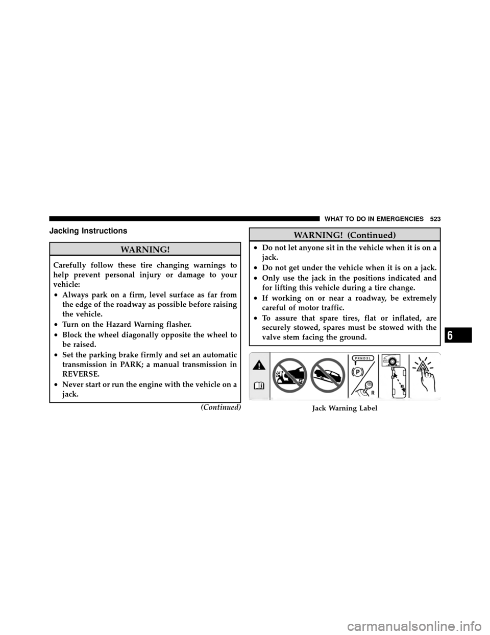
•Block the wheel diagonally opposite the wheel to
be raised.
•Set the parking brake firmly and set an automatic
transmission in PARK; a manual transmission in
REVERSE.
•Never start or run the engine with the vehicle on a
jack.(Continued)
WARNING! (Continued)
•Do not let anyone sit in the vehicle when it is on a
jack.
•Do not get under the vehicle when it is on a jack.
•Only use the jack in the positions indicated and
for lifting this vehicle during a tire change.
•If working on or near a roadway, be extremely
careful of motor traffic.
•To assure that spare tires, flat or inflated, are
securely stowed, spares must be stowed with the
valve stem facing the ground.
Jack Warning Label
6
WHAT TO DO IN EMERGENCIES 523
Page 534 of 643
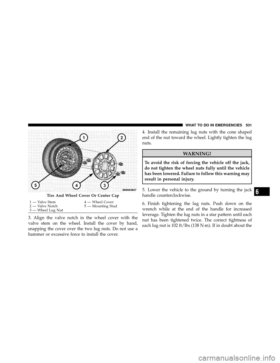
3. Align the valve notch in the wheel cover with the
valve stem on the wheel. Install the cover by hand,
snapping the cover over the two lug nuts. Do not use a
hammer or excessive force to install the cover.4. Install the remaining lug nuts with the cone shaped
end of the nut toward the wheel. Lightly tighten the lug
nuts.
WARNING!
To avoid the risk of forcing the vehicle off the jack,
do not tighten the wheel nuts fully until the vehicle
has been lowered. Failure to follow this warning may
result in personal injury.
5. Lower the vehicle to the ground by turning the jack
handle counterclockwise.
6. Finish tightening the lug nuts. Push down on the
wrench while at the end of the handle for increased
leverage. Tighten the lug nuts in a star pattern until each
nut has been tightened twice. The correct tightness of
each lug nut is 102 ft/lbs (138 N·m). If in doubt about the
Tire And Wheel Cover Or Center Cap
1 — Valve Stem 4 — Wheel Cover
2 — Valve Notch 5 — Mounting Stud
3 — Wheel Lug Nut
6
WHAT TO DO IN EMERGENCIES 531