Page 109 of 652

•Always make sure that objects cannot fall into the
driver footwell while the vehicle is moving. Ob-
jects can become trapped under the brake pedal
and accelerator pedal causing")
WARNING! (Continued)
•Always make sure that objects cannot fall into the
driver footwell while the vehicle is moving. Ob-
jects can become trapped under the brake pedal
and accelerator pedal causing a loss of vehicle
control.
•If required, mounting posts must be properly
installed, if not equipped from the factory.
Failure to properly follow floor mat installation or
mounting can cause interference with the brake
pedal and accelerator pedal operation causing loss
of control of the vehicle.
Periodic Safety Checks You Should Make Outside
The Vehicle
Tires
Examine tires for excessive tread wear and uneven wear
patterns. Check for stones, nails, glass, or other objectslodged in the tread or sidewall. Inspect the tread for cuts
and cracks. Inspect sidewalls for cuts, cracks and bulges.
Check the wheel nuts for tightness. Check the tires
(including spare) for proper cold inflation pressure.
Lights
Have someone observe the operation of exterior lights
while you work the controls. Check turn signal and high
beam indicator lights on the instrument panel.
Door Latches
Check for positive closing, latching, and locking.
Fluid Leaks
Check area under vehicle after overnight parking for fuel,
engine coolant, oil, or other fluid leaks. Also, if gasoline
fumes are detected or if fuel, power steering fluid, or
brake fluid leaks are suspected, the cause should be
located and corrected immediately.
2
THINGS TO KNOW BEFORE STARTING YOUR VEHICLE 107
Page 295 of 652

2. Fully depress the accelerator pedal, slowly, three times
within 10 seconds.
3. Turn the ignition switch to the OFF/LOCK position.
NOTE:If the indicator message illuminates when you
start the engine, the oil change indicator system did not
reset. If necessary, repeat these steps.
Electronic Vehicle Information Center
(EVIC) Display — If Equipped
The Electronic Vehicle Information Center (EVIC) fea-
tures a driver-interactive display that is located in the
instrument cluster. For further information, refer to
“Electronic Vehicle Information Center (EVIC)”.
7. Anti-Lock Brake (ABS) Light This light monitors the Anti-Lock Brake System
(ABS). The light will turn on when the ignition
switch is turned to the ON/RUN position and
may stay on for as long as four seconds. If the ABS light remains on or turns on while driving, it
indicates that the Anti-Lock portion of the brake system
is not functioning and that service is required. However,
the conventional brake system will continue to operate
normally if the BRAKE warning light is not on.
If the ABS light is on, the brake system should be serviced
as soon as possible to restore the benefits of Anti-Lock
brakes. If the ABS light does not turn on when the
ignition switch is turned to the ON/RUN position, have
the light inspected by an authorized dealer.
8. Tire Pressure Monitoring Telltale Light — If
Equipped
Each tire, including the spare (if provided),
should be checked monthly when cold and
inflated to the inflation pressure recommended
by the vehicle manufacturer on the vehicle
placard or tire inflation pressure label. (If your vehicle has
tires of a different size than the size indicated on the
4
UNDERSTANDING YOUR INSTRUMENT PANEL 293
Page 424 of 652

�Driving Through Water ................. 444
▫ Flowing/Rising Water ................. 444
▫ Shallow Standing Water ............... 444
� Power Steering ....................... 446
▫ Power Steering Fluid Check ............. 447
� Parking Brake ........................ 447
� Anti-Lock Brake System (ABS) ............ 450
▫ Anti-Lock Brake Warning Light .......... 451
� Electronic Brake Control System ........... 452
▫ Traction Control System (TCS) ........... 452
▫ Brake Assist System (BAS) .............. 453
▫ Electronic Stability Control (ESC) ......... 454
▫ Hill Start Assist (HSA) ................ 457 �
Tire Safety Information ................. 460
▫ Tire Markings ....................... 460
▫ Tire Identification Number (TIN) ......... 464
▫ Tire Terminology And Definitions ......... 465
▫ Tire Loading And Tire Pressure .......... 466
� Tires — General Information ............. 470
▫ Tire Pressure ....................... 470
▫ Tire Inflation Pressures ................ 471
▫ Tire Pressures For High-Speed Operation . . . 472
▫ Radial-Ply Tires ..................... 473
▫ Spare Tire Matching Original Equipped Tire
And Wheel – If Equipped .............. 473
▫ Compact Spare Tire – If Equipped ........ 474
422 STARTING AND OPERATING
Page 425 of 652

▫Full Size Spare – If Equipped ............ 475
▫ Limited-Use Spare – If Equipped ......... 475
▫ Tire Spinning ....................... 476
▫ Tread Wear Indicators ................. 476
▫ Life Of Tire ........................ 477
▫ Replacement Tires .................... 478
� Tire Chains .......................... 479
� Snow Tires .......................... 480
� Tire Rotation Recommendations ........... 481
� Tire Pressure Monitor System (TPMS) ....... 482
▫ Base System ........................ 485
▫ Premium System – If Equipped .......... 487�
Fuel Requirements ..................... 491
▫ 3.6L Engine ........................ 491
▫ Reformulated Gasoline ................ 491
▫ Gasoline/Oxygenate Blends ............. 492
▫ E-85 Usage In Non-Flex Fuel Vehicles ...... 492
▫ MMT In Gasoline .................... 493
▫ Materials Added To Fuel ............... 493
▫ Fuel System Cautions ................. 493
▫ Carbon Monoxide Warnings ............ 494
� Flexible Fuel — If Equipped .............. 495
▫ E-85 General Information ............... 495
▫ Ethanol Fuel (E-85) ................... 496
▫ Fuel Requirements ................... 496
5
STARTING AND OPERATING 423
Page 463 of 652
 - Metric tire sizing is based on U.S.
design standards. P-Metric tires have the letter “P”
molded into the sidewall preceding the size designa-
tion. Example: P215/65R15 95H")
NOTE:
•P (Passenger) - Metric tire sizing is based on U.S.
design standards. P-Metric tires have the letter “P”
molded into the sidewall preceding the size designa-
tion. Example: P215/65R15 95H.
•European-Metric tire sizing is based on European
design standards. Tires designed to this standard have
the tire size molded into the sidewall beginning with
the section width. The letter�P�is absent from this tire
size designation. Example: 215/65R15 96H.
•LT (Light Truck) - Metric tire sizing is based on U.S.
design standards. The size designation for LT-Metric
tires is the same as for P-Metric tires except for the
letters “LT” that are molded into the sidewall preced-
ing the size designation. Example: LT235/85R16.
•Temporary spare tires are spares designed for tempo-
rary emergency use only. Temporary high pressure
compact spare tires have the letter “T” or “S” molded
into the sidewall preceding the size designation. Ex-
ample: T145/80D18 103M.
•High flotation tire sizing is based on U.S. design
standards and it begins with the tire diameter molded
into the sidewall. Example: 31x10.5 R15 LT.
5
STARTING AND OPERATING 461
Page 464 of 652
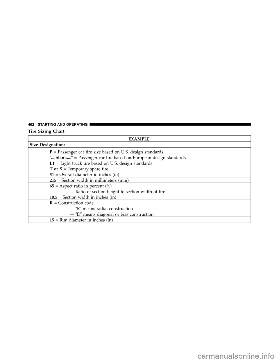
Tire Sizing Chart
EXAMPLE:
Size Designation:
P= Passenger car tire size based on U.S. design standards
�....blank....� = Passenger car tire based on European design standards
LT = Light truck tire based on U.S. design standards
TorS= Temporary spare tire
31 = Overall diameter in inches (in)
215 = Section width in millimeters (mm)
65 = Aspect ratio in percent (%)
— Ratio of section height to section width of tire
10.5 = Section width in inches (in)
R = Construction code
—�R� means radial construction
— �D� means diagonal or bias construction
15 = Rim diameter in inches (in)
462 STARTING AND OPERATING
Page 469 of 652
 number of people that can be carried in the vehicle
2) total weight your vehicle can carry
3) tire size designed for your vehicle
4) cold tir")
This placard tells you important information about
the:
1) number of people that can be carried in the vehicle
2) total weight your vehicle can carry
3) tire size designed for your vehicle
4) cold tire inflation pressures for the front, rear, and
spare tires.
Loading
The vehicle maximum load on the tire must not exceed
the load carrying capacity of the tire on your vehicle. You
will not exceed the tire’s load carrying capacity if you
adhere to the loading conditions, tire size, and cold tire
inflation pressures specified on the Tire and Loading
Information placard and in the “Vehicle Loading” section
of this manual.
NOTE:Under a maximum loaded vehicle condition,
gross axle weight ratings (GAWRs) for the front and rear axles must not be exceeded. For further information on
GAWRs, vehicle loading, and trailer towing, refer to
“Vehicle Loading” in this section.
To determine the maximum loading conditions of your
vehicle, locate the statement “The combined weight of
occupants and cargo should never exceed XXX lbs or
XXX kg” on the Tire and Loading Information placard.
The combined weight of occupants, cargo/luggage and
trailer tongue weight (if applicable) should never exceed
the weight referenced here.
Steps For Determining Correct Load Limit
1. Locate the statement “The combined weight of occu-
pants and cargo should never exceed XXX lbs or XXX kg”
on your vehicle’s placard.
2. Determine the combined weight of the driver and
passengers that will be riding in your vehicle.5
STARTING AND OPERATING 467
Page 475 of 652

WARNING!
High-speed driving, with your vehicle at or above
maximum load, is dangerous. The added strain on
your tires could cause them to fail. You could have a
serious collision. Do not drive a vehicle loaded to the
maximum capacity at continuous speeds above
75 mph (120 km/h).
Radial-Ply Tires
WARNING!
Combining radial ply tires with other types of tires
on your vehicle will cause your vehicle to handle
poorly. The instability could cause a collision. Al-
ways use radial ply tires in sets of four. Never
combine them with other types of tires.Cuts and punctures in radial tires are repairable only in
the tread area because of sidewall flexing. Consult your
authorized tire dealer for radial tire repairs.
Spare Tire Matching Original Equipped Tire And
Wheel – If Equipped
Your vehicle may be equivalent with a spare tire and
wheel in look and function as the original equipment tire
and wheel found on the front or rear axle of your vehicle.
This spare tire may be used in the tire rotation for your
vehicle. If your vehicle has this option refer to an
authorized tire dealer for the recommended tire rotation
pattern.
5
STARTING AND OPERATING 473