Page 362 of 652

•Cycle the ignition to the ON or ACC position.
•Turn on the VES™ player (if equipped on Dual Screen
System) by pushing the Power button, located on the far
left, or by pressing the button on the Remote Control.
•When the Video Screen(s) are open and a DVD is
inserted into the VES™ player, the screen(s) turn(s) on
automatically, the headphone transmitters turn on and
playback begins.
•For Dual Video Screen System, Channel 1 on the
Remote Control and Headphones refers to Screen 1
(second row) and Channel 2 on the Remote Control
and Headphones refers to Screen 2 (third row). Refer
to the Dual Video Screen section for more information.
Play Video Games
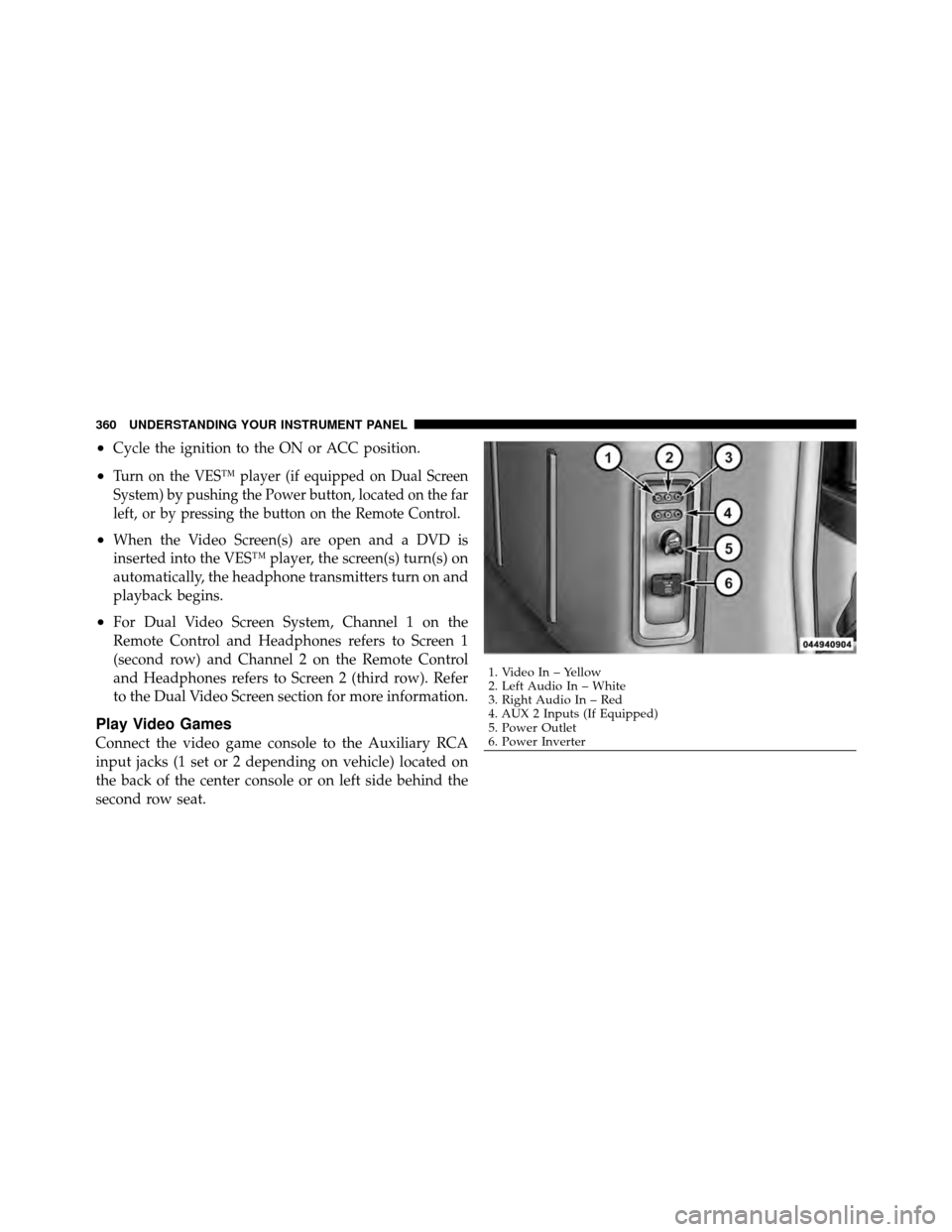
Connect the video game console to the Auxiliary RCA
input jacks (1 set or 2 depending on vehicle) located on
the back of the center console or on left side behind the
second row seat.
1. Video In – Yellow
2. Left Audio In – White
3. Right Audio In – Red
4. AUX 2 Inputs (If Equipped)
5. Power Outlet
6. Power Inverter
360 UNDERSTANDING YOUR INSTRUMENT PANEL
Page 406 of 652
The rear blower and temperature controls for the rear
seat passengers are located in the headliner, near the
center of the vehicle.Rear Blower Control
The primary control for the rear blower is on the front
climate control unit, located on the instrument panel.
Only when the front control for the rear blower is in the
REARposition do the second row seat occupants have
control of the rear blower speed.
The rear blower control, located in the rear overhead
console, has an off position and a range of blower speeds.
This allows the second row seat occupants to control the
volume of air circulated in the rear of the vehicle.
Rear Manual Climate Controls
1 – Rear Blower 3 – Rear Mode
2 – Rear Temperature 4 – Rear Climate Control Lock
404 UNDERSTANDING YOUR INSTRUMENT PANEL
Page 526 of 652
Spare Tire Removal
The spare tire is stowed inside a protective cover located
under the center of the vehicle between the front doors by
means of a cable winch mechanism. The “spare tire
drive” nut is located on the floor, under a plastic cap at
the front of the floor console or under front super console
forward bin liner.
To Access Spare Tire Winch Drive Nut
To access the spare tire winch drive nut and lower the
spare tire, you will need to refer to one of the following
center console configurations.
Super Console
For vehicles equipped with the Super Console, the spare
tire winch assembly drive nut is located beneath the
console.
Spare Tire Location
524 WHAT TO DO IN EMERGENCIES
Page 528 of 652
3. Remove the liner from the console’s storage compart-
ment to access the spare tire winch drive nut.
Premium/Base/Cargo Center Console
Pull the Winch Cover assembly plug (if equipped) to
access the winch drive nut.
Spare Tire Tools
The tool pouch contains three pieces and can be as-
sembled into a spare tire hook; to remove the compact
spare tire/cover assembly from under the vehicle, or a
Winch T-handle; to raise/lower the compact spare tire/
cover assembly.Drive Nut Access
Winch Cover Assembly Plug (If Equipped)
526 WHAT TO DO IN EMERGENCIES
Page 530 of 652
Spare Tire Removal Instructions
The spare tire is located under the vehicle beneath the
center console area.
1. Assemble the spare tire tools into a T-handle and place
the square end over the spare tire winch drive nut.2. Rotate the nut to the left until the winch mechanism
stops turning freely. This will allow enough slack in the
cable to allow you to pull the spare tire out from
underneath the vehicle.
CAUTION!
The winch mechanism is designed for use with the
winch T-handle only. Use of an air wrench or other
power tools is not recommended and can damage the
winch.
3. To remove the compact spare tire/cover assembly,
assemble the winch T-handle extensions to form a spare
tire hook, and pull the spare tire out from under the
vehicle.
Spare Tire And Cover
528 WHAT TO DO IN EMERGENCIES
Page 591 of 652
CavityCartridge
Fuse Mini-
Fuse Description
M1 — 15 Amp BlueRear Center Brake
Lamp/Brake Switch
M2 — 20 Amp YellowTrailer Lighting, Front
Fog Lamps, Intelli-
gent Battery Sensor
(IBS)
M3 — 20 Amp YellowFront/Rear Axle
Locker, Vacuum
Pump Motor
M4 — 10 Amp RedTrailer Tow
M5 — 25 Amp NaturalInverterCavity
Cartridge
Fuse Mini-
Fuse Description
M6 — 20 Amp YellowPower Outlet #1
(ACC), Rain Sensor,
Cigar Lighter (Instru-
ment Panel or with
Console Rear)
M7 — 20 Amp YellowPower Outlet #2
(BATT/ACC SELECT)
– Center Seat or with
Console Rear
M8 — 20 Amp YellowFront Heated Seat – If
Equipped
M9 — 20 Amp YellowRear Heated Seat – If
Equipped
7
MAINTAINING YOUR VEHICLE 589
Page 594 of 652

CavityCartridge
Fuse Mini-
Fuse Description
M32 — 10 Amp RedAirbag Module,
THATCHUM – If
Equipped
M33 — 10 Amp RedPowertrain
M34 — 10 Amp RedPark Assist, Heater
Climate Control Mod-
ule, Headlamp Wash,
Compass, Rear Cam-
era, Door Lamps,
Flashlight, Relay Die-
sel Cabin Heater, Rad
Fan Diesel – If
Equipped
M35 — 10 Amp RedHeated MirrorsCavity
Cartridge
Fuse Mini-
Fuse Description
M36 — 20 Amp YellowPower Outlet #3 (In-
strument Panel or
with Console Center)
M37 — 10 Amp RedAntilock Brakes, Sta-
bility Control, Stop
Lamp, Fuel Pump
M38 — 25 Amp NaturalDoor Lock/Unlock
Motors, Liftgate
Lock/Unlock Motors
The heated mirrors, lower instrument panel power outlet
and removable floor console, when in the front position
are fused with self-resetting fuses that are only service-
able by an authorized dealer. The power seats are fused
by a 30 Amp circuit breaker located under the driver’s
seat. The power windows are fused by a 25 Amp circuit
breaker located under the instrument panel near the
592 MAINTAINING YOUR VEHICLE
Page 595 of 652

steering column. If you experience temporary or perma-
nent loss of these systems, see your authorized dealer for
service.
VEHICLE STORAGE
If you are leaving your vehicle dormant for more than
21 days, you may want to take steps to protect your
battery. You may do the following:
•Remove the 20 Amp mini-fuse in the Totally Inte-
grated Power Module (TIPM) labeled Ignition-Off
Draw (IOD).
•Or, disconnect the negative cable from the battery.
•Anytime you store your vehicle, or keep it out of
service for two weeks or more, run the air conditioning
system at idle for about five minutes in the fresh air
and high blower setting. This will ensure adequate
system lubrication to minimize the possibility of com-
pressor damage when the system is started again.
REPLACEMENT BULBS
LIGHT BULBS – InteriorBulb Number
Center & Rear Dome Lamp ................. 578
Center & Rear Reading Lamps ............... 578
Front Door Courtesy Lamp .................. 578
Front Header Reading Lamps – If Equipped ..... 578
Instrument Cluster Lamps .................PC74
Liftgate Lamp(s) ......................... 578
Overhead Console Reading Lamps ..........PC579
Removable Console Lamp – If Equipped ........ 194
Visor Vanity Lamps .................... 6501966
NOTE: For lighted switches, see your authorized dealer
for replacement instructions.
All of the interior bulbs are glass wedge base or glass
cartridge types. Aluminum base bulbs are not approved
and should not be used for replacement.
7
MAINTAINING YOUR VEHICLE 593