Page 386 of 557

ESC Activation/Malfunction Indicator Light and
ESC OFF Indicator Light
The “ESC Activation/Malfunction Indicator
Light” in the instrument cluster will come on
when the ignition switch is turned to the ON
position. It should go out with the engine
running. If the “ESC Activation/Malfunction Indicator
Light” comes on continuously with the engine running, a
malfunction has been detected in the ESC system. If this
light remains on after several ignition cycles, and the
vehicle has been driven several miles (kilometers) at
speeds greater than 30 mph (48 km/h), see your autho-
rized dealer as soon as possible to have the problem
diagnosed and corrected.
The “ESC Activation/Malfunction Indicator Light” (lo-
cated in the instrument cluster) starts to flash as soon as
the tires lose traction and the ESC system becomes active.
The “ESC Activation/Malfunction Indicator Light” also
flashes when TCS is active. If the “ESC Activation/ Malfunction Indicator Light” begins to flash during ac-
celeration, ease up on the accelerator and apply as little
throttle as possible. Be sure to adapt your speed and
driving to the prevailing road conditions.
NOTE:
•The “ESC Activation/Malfunction Indicator Light”
and the “ESC OFF Indicator Light” come on momen-
tarily each time the ignition switch is turned ON.
•Each time the ignition is turned ON, the ESC system
will be ON even if it was turned off previously.
•The ESC system will make buzzing or clicking sounds
when it is active. This is normal; the sounds will stop
when ESC becomes inactive following the maneuver
that caused the ESC activation.
The “ESC OFF Indicator Light” indicates the
Electronic Stability Control (ESC) is off.
384 STARTING AND OPERATING
Page 387 of 557
Synchronizing ESC
If the power supply is interrupted (battery
disconnected or discharged), the “ESC
Activation/Malfunction Indicator Light” may
illuminate with the engine running. If this
should occur, turn the steering wheel completely to the
left and then to the right. The “ESC Activation/
Malfunction Indicator Light” should go out. However, if
the light remains on, have the ESC and BAS checked at
your authorized dealer as soon as possible.
TIRE SAFETY INFORMATION
Tire Markings
1 — U.S. DOT Safety
Standards Code (TIN) 4 — Maximum Load
2 — Size Designation 5 — Maximum Pressure
3 — Service Description 6 — Treadwear, Traction and
Temperature Grades
5
STARTING AND OPERATING 385
Page 388 of 557
 - Metric tire sizing is based on U.S.
design standards. P-Metric tires have the letter “P”
molded into the sidewall preceding the size designa-
tion. Example: P215/65R15 95H")
NOTE:
•P (Passenger) - Metric tire sizing is based on U.S.
design standards. P-Metric tires have the letter “P”
molded into the sidewall preceding the size designa-
tion. Example: P215/65R15 95H.
•European-Metric tire sizing is based on European
design standards. Tires designed to this standard have
the tire size molded into the sidewall beginning with
the section width. The letter�P�is absent from this tire
size designation. Example: 215/65R15 96H.
•LT (Light Truck) - Metric tire sizing is based on U.S.
design standards. The size designation for LT-Metric
tires is the same as for P-Metric tires except for the
letters “LT” that are molded into the sidewall preced-
ing the size designation. Example: LT235/85R16.
•Temporary spare tires are spares designed for tempo-
rary emergency use only. Temporary high pressure
compact spare tires have the letter “T” or “S” molded
into the sidewall preceding the size designation. Ex-
ample: T145/80D18 103M.
•High flotation tire sizing is based on U.S. design
standards and it begins with the tire diameter molded
into the sidewall. Example: 31x10.5 R15 LT.
386 STARTING AND OPERATING
Page 389 of 557
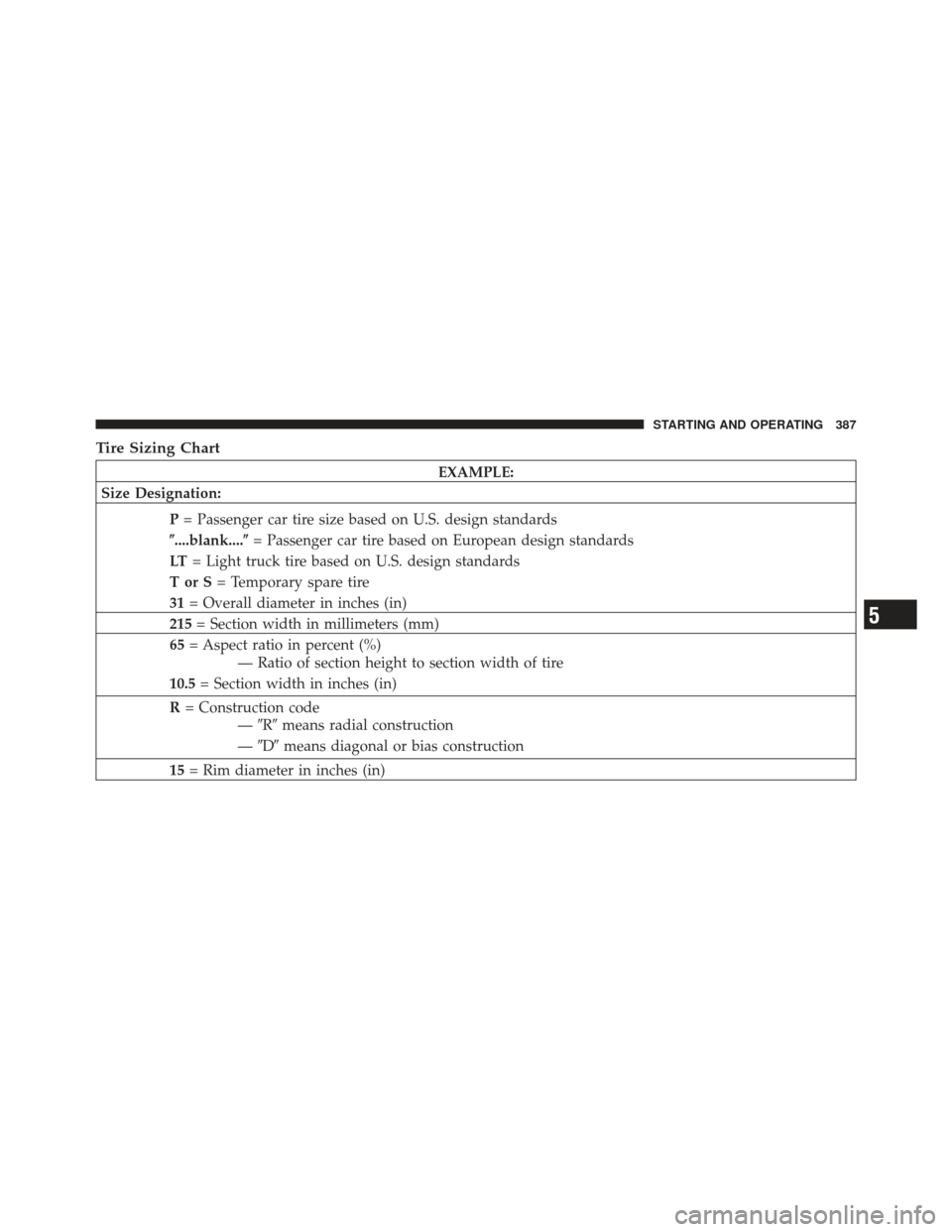
Tire Sizing Chart
EXAMPLE:
Size Designation:
P= Passenger car tire size based on U.S. design standards
�....blank....� = Passenger car tire based on European design standards
LT = Light truck tire based on U.S. design standards
TorS= Temporary spare tire
31 = Overall diameter in inches (in)
215 = Section width in millimeters (mm)
65 = Aspect ratio in percent (%)
— Ratio of section height to section width of tire
10.5 = Section width in inches (in)
R = Construction code
—�R� means radial construction
— �D� means diagonal or bias construction
15 = Rim diameter in inches (in)
5
STARTING AND OPERATING 387
Page 390 of 557

EXAMPLE:
Service Description: 95= Load Index
— A numerical code associated with the maximum load a tire can carry
H = Speed Symbol
— A symbol indicating the range of speeds at which a tire can carry a load corresponding
to its load index under certain operating conditions
— The maximum speed corresponding to the speed symbol should only be achieved under
specified operating conditions (i.e., tire pressure, vehicle loading, road conditions, and
posted speed limits)
Load Identification: �....blank....� = Absence of any text on the sidewall of the tire indicates a Standard Load (SL) tire
Extra Load (XL) = Extra load (or reinforced) tire
Light Load (LL) = Light load tire
C, D, E, F, G = Load range associated with the maximum load a tire can carry at a specified pressure
Maximum Load — Maximum load indicates the maximum load this tire is designed to carry
Maximum Pressure — Maximum pressure indicates the maximum permissible cold tire inflation pressure for
this tire
388 STARTING AND OPERATING
Page 403 of 557

Keep dismounted tires in a cool, dry place with as little
exposure to light as possible. Protect tires from contact
with oil, grease, and gasoline.
Replacement Tires
The tires on your new vehicle provide a balance of many
characteristics. They should be inspected regularly for
wear and correct cold tire inflation pressure. The manu-
facturer strongly recommends that you use tires equiva-
lent to the originals in size, quality and performance
when replacement is needed. (Refer to the paragraph on
“Tread Wear Indicators”). Refer to the “Tire and Loading
Information” placard for the size designation of your tire.
The Load Index and Speed Symbol for your tire will be
found on the original equipment tire sidewall. See the
Tire Sizing Chart example found in the Tire Safety
Information section of this manual for more information
relating to the Load Index and Speed Symbol of a tire.It is recommended to replace the two front tires or two
rear tires as a pair. Replacing just one tire can seriously
affect your vehicle’s handling. If you ever replace a
wheel, make sure that the wheel’s specifications match
those of the original wheels.
It is recommended you contact your original equipment
or an authorized tire dealer with any questions you may
have on tire specifications or capability. Failure to use
equivalent replacement tires may adversely affect the
safety, handling, and ride of your vehicle.
5
STARTING AND OPERATING 401
Page 408 of 557

The Tire Pressure Monitor System (TPMS) will warn the
driver of a low tire pressure based on the vehicle recom-
mended cold placard pressure.
The tire pressure will")
TIRE PRESSURE MONITOR SYSTEM (TPMS)
The Tire Pressure Monitor System (TPMS) will warn the
driver of a low tire pressure based on the vehicle recom-
mended cold placard pressure.
The tire pressure will vary with temperature by about
1 psi (6.9 kPa) for every 12°F (6.5°C). This means that
when the outside temperature decreases, the tire pressure
will decrease. Tire pressure should always be set based
on cold inflation tire pressure. This is defined as the tire
pressure after the vehicle has not been driven for at least
three hours, or driven less than 1 mile (1.6 km) after a
three hour period. The cold tire inflation pressure must
not exceed the maximum inflation pressure molded into
the tire sidewall. Refer to “Tires – General Information”
in “Starting and Operating” for information on how to
properly inflate the vehicle’s tires. The tire pressure will
also increase as the vehicle is driven - this is normal and
there should be no adjustment for this increased pres-
sure.The TPMS will warn the driver of a low tire pressure if
the tire pressure falls below the low-pressure warning
limit for any reason, including low temperature effects
and natural pressure loss through the tire.
The TPMS will continue to warn the driver of low tire
pressure as long as the condition exists, and will not turn
off until the tire pressure is at or above the recommended
cold placard pressure. Once the low tire pressure warn-
ing (Tire Pressure Monitoring [TPM] Telltale Light) illu-
minates, you must increase the tire pressure to the
recommended cold placard pressure in order for the TPM
Telltale Light to turn off. The system will automatically
update and the TPM Telltale Light will turn off once the
system receives the updated tire pressures. The vehicle
may need to be driven for up to 20 minutes above 15 mph
(24 km/h) in order for the TPMS to receive this informa-
tion.
406 STARTING AND OPERATING
Page 409 of 557
 placard pressure
of 30 psi (207 kPa). If the ambient temperature is 68°F
(20°C) and the measured tire pressur")
For example, your vehicle may have a recommended
cold (parked for more than three hours) placard pressure
of 30 psi (207 kPa). If the ambient temperature is 68°F
(20°C) and the measured tire pressure is 27 psi (186 kPa),
a temperature drop to 20°F (-7°C) will decrease the tire
pressure to approximately 23 psi (158 kPa). This tire
pressure is sufficiently low enough to turn ON the TPM
Telltale Light. Driving the vehicle may cause the tire
pressure to rise to approximately 27 psi (186 kPa), but the
TPM Telltale Light will still be ON. In this situation, the
TPM Telltale Light will turn OFF only after the tires are
inflated to the vehicle’s recommended cold placard pres-
sure value.CAUTION!
•The TPMS has been optimized for the original
equipment tires and wheels. TPMS pressures and
warning have been established for the tire size
equipped on your vehicle. Undesirable system
operation or sensor damage may result when us-
ing replacement equipment that is not of the same
size, type, and/or style. Aftermarket wheels can
cause sensor damage. Do not use aftermarket tire
sealants or balance beads if your vehicle is
equipped with a TPMS, as damage to the sensors
may result.
•After inspecting or adjusting the tire pressure,
always reinstall the valve stem cap. This will
prevent moisture and dirt from entering the valve
stem, which could damage the TPM sensor.
5
STARTING AND OPERATING 407
, the “ESC
Activation/Malfunction Indicator Light” may
illuminate with the engine running. If this
should o")