Page 41 of 60

Black plate (11,1)Chevrolet Tahoe Police and Special Service Packages - 2012
Special Equipment Options 15-11
Exterior Lamp
Emergency Flashing
System - SEO 6J7
SEO 6J7 provides a high-beam
headlamps flashing module, rear
lamps flashing and control wire for a
customer-furnished switch to turn
the module on or off. The flasher
control wire is coiled under the
center of the instrument panel. This
control lead may be combined with
the interior wiring leads for SEO 6J3
when that option is ordered with
SEO 6J7.The headlamps flashing module is
located below the passenger side
front headlamp and forward of the
passenger side front wheel. The
module is connected to an inline
connector in the forward lamp
harness. The headlamps flashing
module is activated by the
application of 12 volts to a dark
green/red wire coiled in the
passenger side footwell. When
activated, the driver and passenger
side high-beam headlamps and the
high-beam instrument panel cluster
light will flash alternately at
2.4 flashes per second.
When the headlamps flashing
module is turned on, the module
sends a signal to the Body Control
Module (BCM). The BCM alternately
flashes the stop lamps and backup
lamps. Depressing the brake pedal
will override the stop lamp flashing
and placing the transmission in
reverse will override the backup
lamp flashing.Activation of the headlamp and
rearlamp flashing can be separated.
Call Kerr Industries at 905‐725‐6561
During daylight conditions, the
Daytime Running Lamps (DRL) are
automatically turned off whenever
the headlamps flasher module is
activated. During nighttime
conditions, the low-beam
headlamps turn on automatically
while the high-beam headlamps
flash. Turning on the high-beam
headlamps manually with the turn
signal/multifunction lever will
override the flashing module and
the high-beam headlamps will
operate continuously.
Page 50 of 60
Black plate (20,1)Chevrolet Tahoe Police and Special Service Packages - 2012
15-20 Special Equipment Options
Maintenance
The emergency roof light circuit is
fed from the fuse labeled Sunroof
located in the underhood electrical
center. Always replace the fuse with
a 30 amp mini-fuse.
Wiring Provisions
for Horn/Siren
Circuit - SEO 6J4
This provision permits customer
connection of a switch to select
either horn or siren operation when
the horn pad is pressed.A 0.35 mm² (22 gauge) wire is
connected to an in-line connector in
the horn circuit of the instrument
panel harness under the instrument
panel. The end of this harness
extension is in a 1.5 m (5 ft) loop of
wire coiled under the center of the
instrument panel.
Page 52 of 60

Black plate (22,1)Chevrolet Tahoe Police and Special Service Packages - 2012
15-22 Special Equipment Options
Wiring Provisions for
Vehicle Grille Lamps,
Flasher, and Speaker/
Siren - SEO 6J3
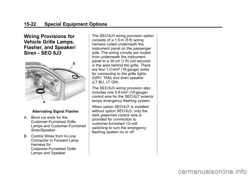
Alternating Signal Flasher
A. Blunt cut ends for the Customer-Furnished Grille
Lamps and Customer-Furnished
Siren/Speaker
B. Control Wires from In-Line Connector in Forward Lamp
Harness for
Customer-Furnished Grille
Lamps and Speaker The SEO 6J3 wiring provision option
consists of a 1.5 m (5 ft) wiring
harness coiled underneath the
instrument panel on the passenger
side. The wiring circuits are routed
from underneath the instrument
panel to a 30 cm (1 ft) coil secured
in the area behind the grille. There
are four 1.0 mm² (16 gauge) wires
for connecting to the grille lights
(GRY, TAN) and siren speaker
(LT BU, LT GN)
The SEO 6J3 wiring provision also
includes one 0.8 mm² (18 gauge)
control wire for the SEO 6J7 exterior
lamps emergency flashing system.
When option SEO 6J7 is installed
without option SEO 6J3, only the
dark green/red control wire is
provided for connection to
customer-furnished 12-volt
switching to turn the emergency
flashing system on or off.
Page 54 of 60

Black plate (24,1)Chevrolet Tahoe Police and Special Service Packages - 2012
15-24 Special Equipment Options
Wiring Provisions Front
Speakers - SEO WX7
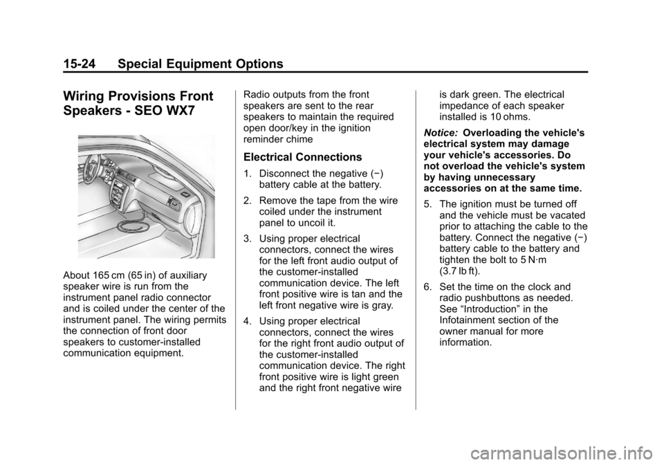
About 165 cm (65 in) of auxiliary
speaker wire is run from the
instrument panel radio connector
and is coiled under the center of the
instrument panel. The wiring permits
the connection of front door
speakers to customer-installed
communication equipment.Radio outputs from the front
speakers are sent to the rear
speakers to maintain the required
open door/key in the ignition
reminder chime
Electrical Connections
1. Disconnect the negative (−)
battery cable at the battery.
2. Remove the tape from the wire coiled under the instrument
panel to uncoil it.
3. Using proper electrical connectors, connect the wires
for the left front audio output of
the customer-installed
communication device. The left
front positive wire is tan and the
left front negative wire is gray.
4. Using proper electrical connectors, connect the wires
for the right front audio output of
the customer-installed
communication device. The right
front positive wire is light green
and the right front negative wire is dark green. The electrical
impedance of each speaker
installed is 10 ohms.
Notice: Overloading the vehicle's
electrical system may damage
your vehicle's accessories. Do
not overload the vehicle's system
by having unnecessary
accessories on at the same time.
5. The ignition must be turned off and the vehicle must be vacated
prior to attaching the cable to the
battery. Connect the negative (−)
battery cable to the battery and
tighten the bolt to 5 N·m
(3.7 lb ft).
6. Set the time on the clock and radio pushbuttons as needed.
See “Introduction” in the
Infotainment section of the
owner manual for more
information.